Clock/timer installation – American Time Wireless Digital 2.3 Elapsed Timer with Code Blue User Manual
Page 5
© American Time & Signal Co.
Appendix
Maintenance
Code Blue
Operation
Contr
ol Station
Clock/Timer
4
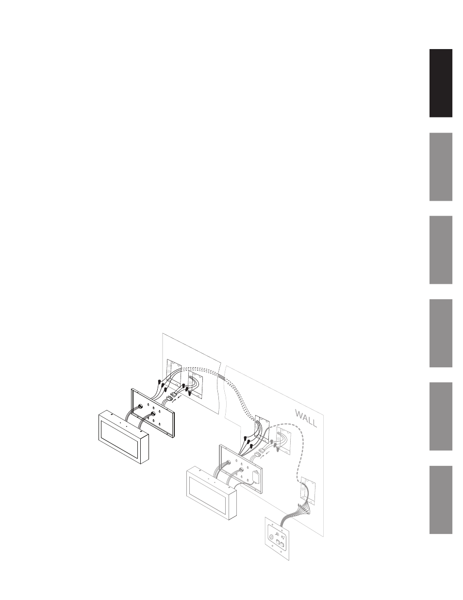
Clock/Timer Installation
For the SQA261RSAES Digital Clock/Timer
The Digital Clock/Timer can be mounted to a single or double gang box. The secondary bushing is to be used for the control
station and SQA261RSAEAS communication low voltage wiring. To install the Digital Clock/Timer, follow the instructions
below.
Ensure that installation conforms to the National Electrical Code and local wiring codes.
CAUTION: Electric Shock Hazard! Disconnect and lock out power to the electrical box before installing or servicing the
clock.
u
Disassemble back plate from the clock (A) by removing the 4 sheet metal screws (2 top and 2 bottom). Be sure to keep
the screws for reassembly.
v
Make electrical connections in gang box (G) (hot, neutral, ground wires) to non-switched electrical circuit wiring using
UL approved wire nuts. Route field wiring away from sharp projections, corners and internal components. For Molex,
white to negative/common, black to ositive/hot and green to ground.
w
Join the two Molex connectors (B) together, placing excess wiring and Molex connectors into the gang box (D).
x
Connect the 3-Communication Wire (C) which will be wired to the SQA261RSAEA (master clock) using UL approved wire
nuts. See wiring details on page 5.
y
Mount back cover (A) to electrical box (D) using 2 screws (single gang) or 4 screws (double gang). Screws not provided.
z
Assemble the clock cover (E) to the back plate (A) using the screws saved in Step 1 above.
Install SQA261RSAEA (master clock) before applying power to the circuit. See page 6.
CAUTION: Electric Shock Hazard! When installing, route field wiring away from sharp projections, corners, and internal
components.
A
C
D
E
F
G
B
See page 6 for Master Clock
Installation Instructions