Clock/timer installation – American Time Wireless Digital 2.3 Elapsed Timer with Code Blue User Manual
Page 7
© American Time & Signal Co.
6
Clock/Timer Installation
Appendix
Maintenance
Code Blue
Operation
Contr
ol Station
Clock/Timer
For the SQA261RSAE & SQA261RSAEA Digital Clock/Timers
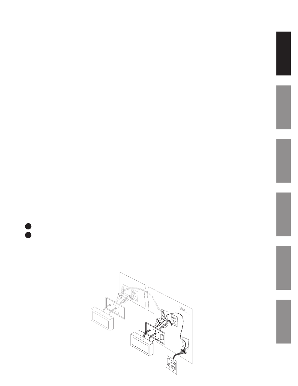
The Digital Clock/Timer can be mounted to a single or double gang box. The secondary bushing is to be used for the conrol
station and SQA261RSAEAS communication low voltage wiring. To install the Digital Clock/Timer, follow the instructions
below.
Ensure that installation conforms to the National Electrical Code and local wiring codes.
CAUTION: Electric Shock Hazard! Disconnect and lock out power to the electrical box before installing or servicing the
clock.
u
Disassemble back plate from the clock (A) by removing the 4 sheet metal screws (2 top and 2 bottom). Be sure to
keep the screws for reassembly.
v
Pull the eight wires of the control station bundle (B) through the secondary bushing of the back plate (A).
w
Make electrical connections in gang box (D) (hot, neutral, ground wires) to non-switched electrical circuit wiring using
UL approved wire nuts. Route field wiring away from sharp projections, corners and internal components. For Molex,
white to negative/common, black to ositive/hot and green to ground.
x
Join the two Molex connectors (C) together, placing excess wiring and Molex connectors into the gang box (D).
y
If installing an SQA261RSAEA (Master Clock) connect the 3 Interconnecting Wires (J) from the SQA261RSAES (Slave
Clock) using UL approved wire nuts.
z
Mount back cover (A) to electrical box (D) using 2 screws (single gang) or 4 screws (double gant). Screws not provided.
Make electrical connections from the ATSTCS Control Station (G) to the clock with the eight (8) wires from the control
station (H) at this time. See wiring detail on page 8.
Connect the RJ11 connector (E) and harness into the RJ11 socket in the receiver module.
Assemble the clock cover (F) to the back plate (A) using the screws saved in Step 1 above.
Make sure the SiteSync IQ system controller and other equipment is set up and operational.
n
Note: Clocks should be installed within 24 hours of installing the system controller. After 24 hours, the system controller will
enter Quiet Mode. Pressing 3-5-7 on the keypad will disable Quiet Mode for 6 hours.
Apply power to the circuit and confirm correct operation.
Upon startup, the clock will flash the version number and then correct with the first valid signal. This should take less
than one minute. If the clock is not updating, review the steps listed above and consult the SiteSync IQ Installation and
Operation Manual for additional troubleshooting assistance. If SQA261RSAES was installed, it will copy the display of
the SQA261RSAEA.
CAUTION: Electric Shock Hazard! When installing, route field wiring away from sharp projections, corners, and internal
components.
11
12
(3) WIRES - ONLY USED
WITH SLAVE CLOCK
A
B
C
D
E
F
G
H
I
J