Control station installation instructions – American Time Wireless Digital 2.3 Elapsed Timer with Code Blue User Manual
Page 9
© American Time & Signal Co.
Appendix
Maintenance
Code Blue
Operation
Contr
ol Station
Clock/Timer
8
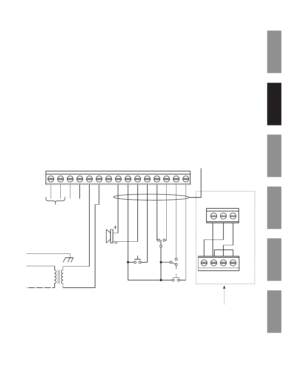
Control Station Installation Instructions
The ATSTCS Control Station can be mounted to a double gang box, 1
1
/
2
inch deep or deeper. The Control Station can be
mounted up to 30 feet away from the Digital Clock/Timer. The recommended minimum interconnecting field wire size is
#22.8 AWG stranded wire.
Ensure that installation conforms to the National Electrical Code and local wiring codes.
CAUTION: Electric Shock Hazard! Ensure that no electrical power is present on any wire before installation.
u
Pull interconnecting field wires into the double gang box.
v
Connect field wiring interconnecting the ATSTCS Control Station with the Digital Clock/Timer to the appropriate wires of
the Control Station. See wiring detail below.
w
Mount the Control Station to the double gang box using the machine screws provided.
K2+
K2–
K1+
K1–
12V
AC
12V
AC
UNREG
GND
PIEZ
O
S5
S4
S3
S2
S1
K2+
K2–
K1+
K1–
GND
CLK
D
AT
A
RED
BLA
CK
VIOLE
T
GRE
Y
BR
OWN
BL
UE
OR
ANGE
YELL
OW
CHASSIS
NEUTRAL
120VAC
TERMINALS K2+ AND K2– ARE USED FOR CODE BL
UE MODE
Typical wiring for the Master Digital Timer with Control Station
PIEZO
BUZZER
30 ft. maximum
#22 AWG wire
(minimum) with
1/32” insulation
(minimum)
RESET
ENTER
START/STOP
INCREMENT
UP
CL
OCK
DOWN
SET
RUN
LABEL #
H004273M
M
ast
er Clock
Ter
minal Block
Sla
ve Clock
Ter
minal Block
n
Note: Just for use if installing
master/slave clocks.