AMETEK CW-M Corrected Table 4-2 in User Manual
AMETEK Equipment
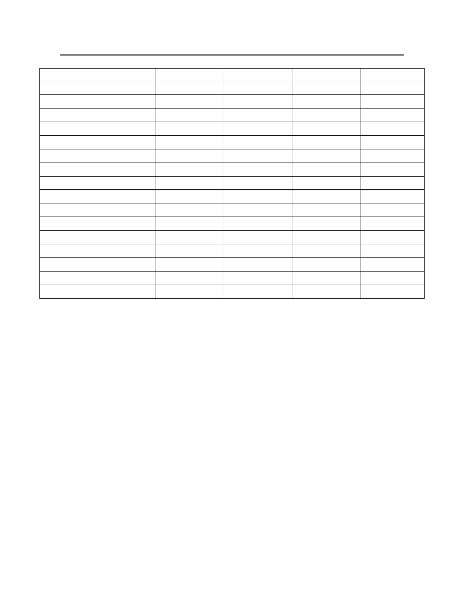
CORRECTED TABLE 4-2 PHASE ANGLE SETTINGS – CW-M SERIES
Leading Phase Angle
Switch 9
Switch 10
Switch 11
Switch 12
0
°
ON
ON
ON
ON
30
°
ON
OFF
ON
ON
45
°
OFF
ON
ON
ON
60
°
OFF
OFF
ON
ON
90
°
ON
ON
ON
OFF
120
°
ON
OFF
ON
OFF
135
°
OFF
ON
ON
OFF
150
°
OFF
OFF
ON
OFF
180
°
ON
ON
OFF
ON
210
°
ON
OFF
OFF
ON
225
°
OFF
ON
OFF
ON
240
°
OFF
OFF
OFF
ON
270
°
ON
ON
OFF
OFF
300
°
ON
OFF
OFF
OFF
315
°
OFF
ON
OFF
OFF
330
°
OFF
OFF
OFF
OFF
The front panel display for B Phase and C Phase units will display the leading
phase angle in degrees.
Typical 3 phase setup:
The A Phase at 0
°, or reference phase. Switches 9 through 12 should be ON
for the A Phase Master CW-M Unit to set 0
°.
The B Phase is set for a +240
° or 240° leading phase angle (same as a -120° or
120
° lagging phase angle) relative to A Phase at 0° Reference. This would
have Switch 9 OFF, Switch 10 OFF, Switch 11 OFF, and switch 12 ON.
The C Phase is set for a +120
° or 120° leading phase angle (same as a -240° or
240
° lagging phase angle) relative to A Phase at 0° Reference. This would
have Switch 9 ON, Switch 10 OFF, Switch 11 ON, and switch 12 OFF.
In this fashion, the phase rotation/sequence will be A-B-C-A-B-C etc.