AMETEK ASD Series Quick Start User Manual
AMETEK Equipment
ASD 30kW Quick Reference Guide - rev X1
© 2011 AMETEK Programmable Power, Inc. All rights reserved.
www.programmablepower.com
Q
UICK
R
EFERENCE
G
UIDE
:
ASD 30kW Water Cooled DC Power Supply
The operation of the Sorensen ASD 30 kW Water Cooled power supply consists of providing water cooling, connecting
the output load, applying the AC mains voltage, programming the output via the analog or digital interface, and monitoring
operation via front panel LEDs and the interfaces.
Water Cooling
Water cooling at a nominal rate of 1.5 gallons per minute (1.25 gpm min, to 2 gpm max) must be provided whenever
the power supply output is enabled, independent of the output current and voltage. The nominal coolant inlet
temperature is 25 °C and must not exceed 30 °C. When the cooling water is above 30 °C and depending on the
operating conditions (e.g. output voltage and current), the modules may give warnings to indicate that they are
approaching an over-temperature protection (OTP). In case of a module OTP, only the module with the over-
temperature will shut-down, the rest would keep operating as normal. Warnings and faults are indicated with red color
LEDs and the corresponding bit in the digital interface.
The coolant source is applied to the connection labeled “WATER INLET” on the rear panel. The coolant return is
applied to the connection labeled “WATER OUTLET”. Both liquid coolant connections are 3/8-18 NPTF.
Output Load Connection
The output load connections are made at bus bars on the rear panel. Load cables (including the terminations) must
be sized for the maximum output current of the unit (500 A for a 60 V unit and 750 A for a 40 V unit).
The bottom bus bar is the negative output. The top bus bar is the positive output. Each bus bar has two 3/8-16 PEM-
nuts to mount the output cables or vertical interconnecting bus bars.
There is a remote sensing connector available to sense the output voltage with better accuracy. The positive sense
point is connected to Remote Sense terminal 1. The negative sense point is connected to Remote Sense terminal 3.
Remote Sense terminal 2 is not used. If not used, remote sensing should be disabled with the switches and/or the
digital interface.
AC Mains Connection
The nominal mains voltage is 380 to 400 Vrms line-to-line (D model), and 480 Vrms line-to-line (E model), 50/60 Hz,
three phases. Under low-line conditions the maximum mains current is 63 Arms (342Vrms input) or 50Arms
(432Vrms input) at full output load. The AC mains and earth ground wires must be sized accordingly.
Connect the 3 phase line voltage with appropriately sized cables to the
“AC INPUT” Phoenix Contact terminal block
on the rear panel. Connect the earth ground wire to the PE terminal adjacent to the AC INPUT terminals.
Front Panel Indicators
Visual indication of the power supply status is available via LEDs on the front panel.
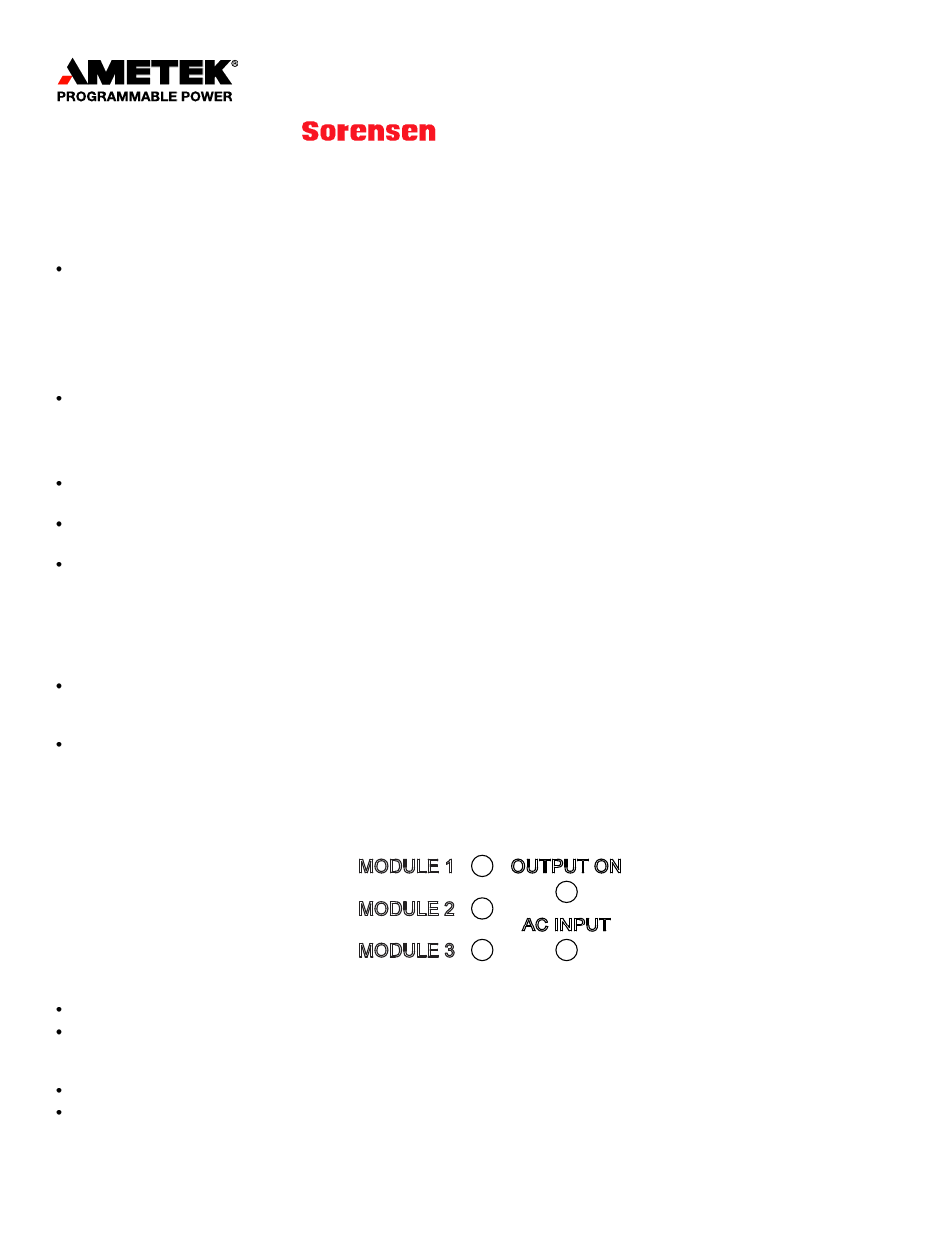
Figure 1: LEDs on the front panel.
The LEDs labeled
“MODULE 1/2/3” indicate the status of the respective modules within the power supply.
Module 1 is the module located, looking at the front panel, at the left side of the unit, module 2 is the module in the
center and module 3 is the module at the right side. Green lights indicate normal active operation. Red lights indicate
that the particular module has detected a warning or fault condition.
The LED labeled “OUTPUT ON” is green when the power supply has set the output to active mode.
The LED labeled “AC INPUT” is normally green. The LED is red when the power supply has detected an internal fault
or warning condition.