Aplex Technology APC-3517B User Manual
Page 21
Advertising
APC-3X17B User Manual
21
C A
CRT_V_SYNC
9 10
CRT_DDCCL
K
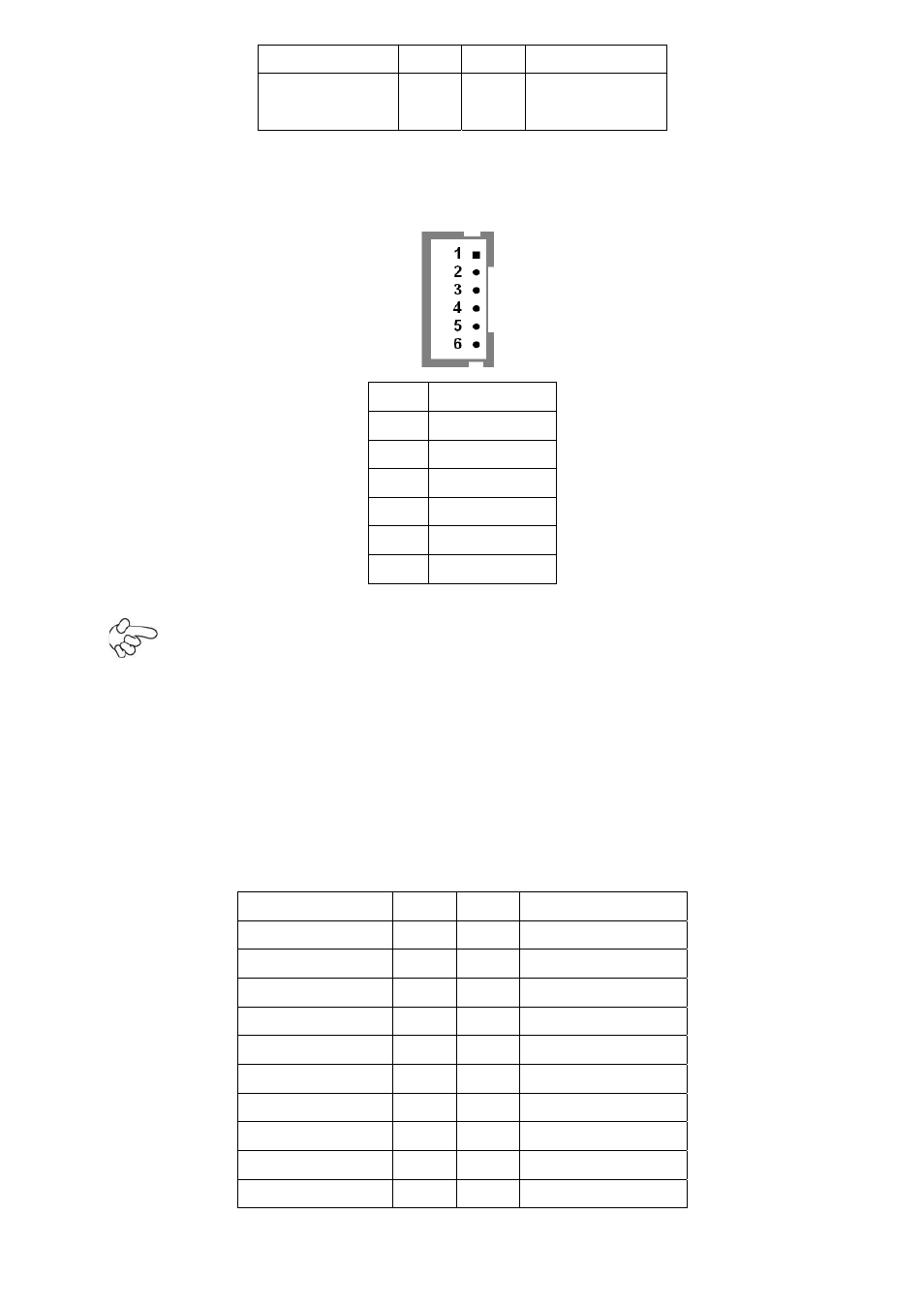
12. INVERTER1:
(2.0mm Pitch 1x6 box Pin Header), Backlight control connector for LVDS1.
Pin# Signal
Name
1 +DC12V
2 +DC12V
3 Ground
4 Ground
5 BKLT_EN
6 BKLT_CTRL
Note:
Pin6 is backlight control signal, support DC or PWM mode, mode select at BIOS CMOS
menu.
13. LVDS1:
(1.25mm Pitch 2x20 Connector), For 18/24-bit LVDS output connector, Fully supported
by Intel GM45 chipset, the interface features dual channel 18/24-bit output.
Signal Name
Pin#
Pin# Signal
Name
VDD5 2
1
VDD5
Ground 4
3
Ground
VDD33 6
5
VDD33
LB_D0_N 8
7
LA_D0_N
LB_D0_P 10
9
LA_D0_P
Ground 12
11
Ground
LB_D1_N 14
13
LA_D1_N
LA_D1_P 16
15
LA_D1_P
Ground 18
17
Ground
LB_D2_N 20
19
LA_D2_N
Advertising