Appendix iii-dispenser kit installation – Argox OS-2130D User Manual
Page 36
58
OS-2130D & OS-2130DE User’s Manual
Appendix III-Dispenser kit Installation
1. Turn off the power switch.
2. Unwrap the PC bag of dispenser kit to take out the screw, the
shaft, the plastic roller, the dispenser bar, the direction label and
the peeler sensor cable.
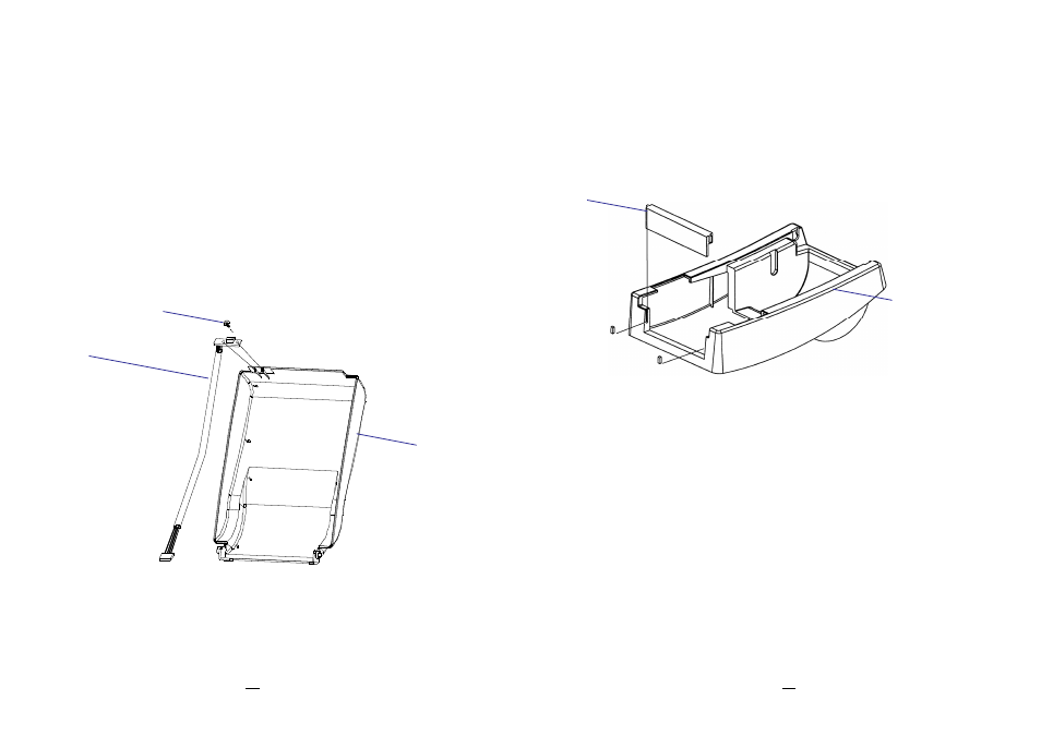
3. Take off the top cover of the printer.
4. Fix the sensor board on the top cover and secure the screw.
Keep the cable at the left.
5. Rout the peeler sensor cable through the guides along the left
side of the top cover.
Figure 6.5
Sensor Cable
Top Cover
Screwe
59
OS-2130D & OS-2130DE User’s Manual
6. Release the two screws at the bottom of the base housing shown
in Figure 6.1 to 6.3.
7. Remove the middle cover.
8. Take off the H cover.
9. Tape the direction label on the top of the H cover with the arrow
sign heading toward the opposite of you.
10. Release the screw on the left bracket of the chassis.
11. Unlatch the print head module. Hook the white roller on the
brackets of the chassis, ensuring the long thinner end at the left
side.
12. Guide the shaft and go through the respective holes on the left
bracket, the white roller, and the right bracket in order (To smooth
this procedure, better hold the white roller with one hand.).
13. Secure the attached screw at right bracket of the chassis to fix
the shaft.
14. Hook the dispenser bar on the brackets of the chassis,
positioning it above the white roller. Ensure that the dispenser bar
is paralleled with the black platen roller and its long thinner end is
H Cover
Middle Cover