Argox OS-2130D User Manual
Page 37
Advertising
60
OS-2130D & OS-2130DE User’s Manual
at that left.
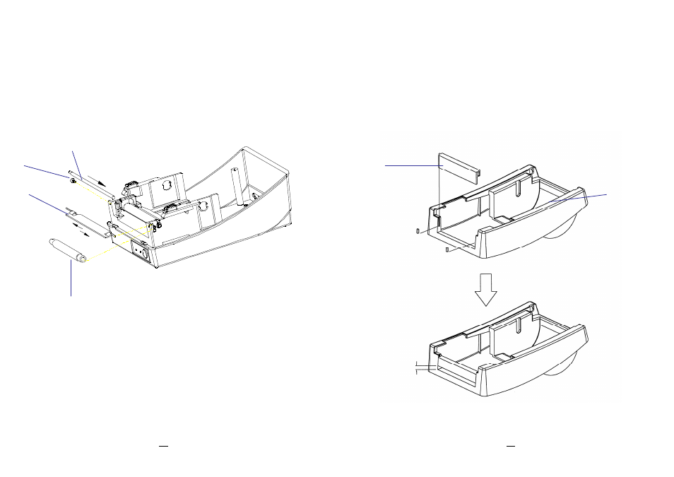
15. Plug the sensor board’s connector into the PCB's header
connector (J2).
16. Secure back the screw on the left bracket of the chassis.
17. Guide the sensor cable connector through the hole on the upper
left corner of the middle cover.
Figure 6.7
Screw
Dispenser bar
White plastic roller
Shaft
61
OS-2130D & OS-2130DE User’s Manual
18. Click the top cover back to the middle cover.
19. Insert the sensor connector into its receptacle on the main logic
board of the base housing.
20. Click the middle cover back to the base housing. First click in the
front part then the rear.
21. Secure the two screws at the bottom of the base housing.
Figure 6.8
4mm Gap
Middle Cover
H. Cover
Advertising