2 connectors, 1 faceplate connectors, Table 3-2 – Artesyn ATCA-7368 Installation and Use (June 2014) User Manual
Page 62: Rj45 female serial line connector pinout, Controls, indicators, and connectors
Advertising
Controls, Indicators, and Connectors
ATCA-7368 Installation and Use (6806800M12D)
62
Base-IF and faceplate Ethernet activity can be seen through FPGA LEDs B1/U1, B2/U2 and U3.
3.2.2
Connectors
3.2.2.1
Faceplate Connectors
Hot Swap
Blue
FRU State Machine
During blade installation
–
Blue: Onboard IPMC powers up
–
Blue (blinking): Blade is communicating with the shelf manager
–
Off: Blade is active
During blade removal
–
Blue (blinking): Blade is notifying the shelf manager that it is
going to deactivate
–
Blue: Blade is ready to be extracted
Table 3-1 Faceplate LEDs (continued)
Indicator
Color
Description
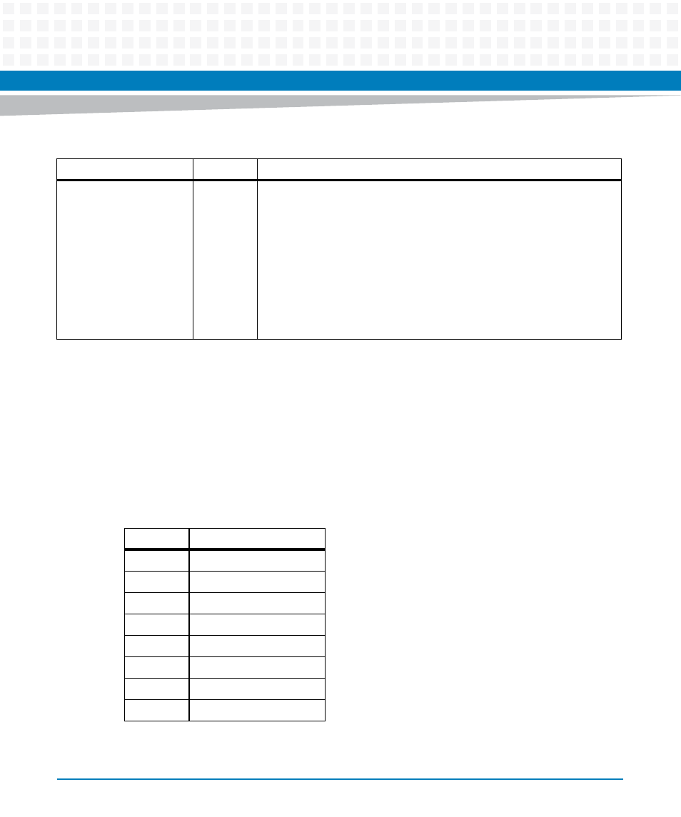
Table 3-2 RJ45 female Serial Line Connector Pinout
Pin
Signal
1
RTS
2
DTR
3
TXD
4
GND
5
GND
6
RXD
7
DSR
8
CTS
Advertising
This manual is related to the following products: