3 onboard connectors, 1 usb2.0 flash connector, 2 backplane connectors – Artesyn ATCA-7368 Installation and Use (June 2014) User Manual
Page 64: Figure 3-3, Usb2.0 flash disk module connector pinout, Table 3-5, Zone 1 connector p1 pin assignment
Advertising
Controls, Indicators, and Connectors
ATCA-7368 Installation and Use (6806800M12D)
64
3.3
Onboard Connectors
3.3.1
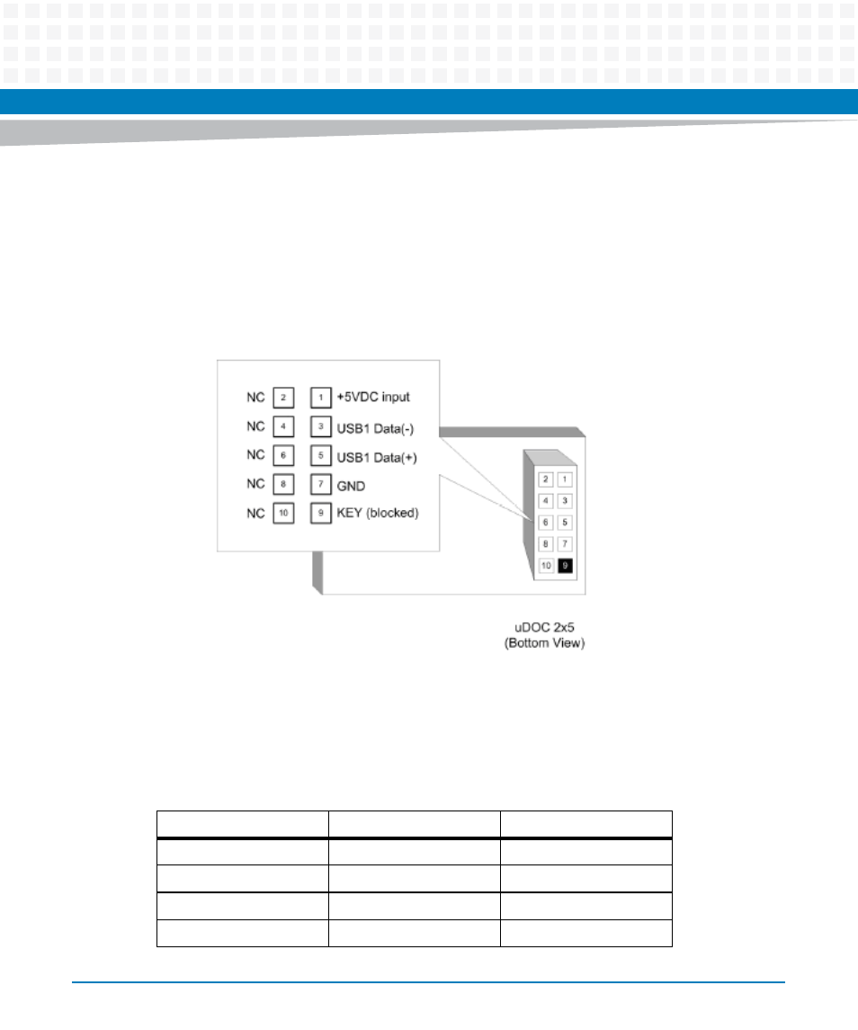
USB2.0 FLASH Connector
One USB Port of ICH10R is connected to the onboard USB Flash Disk Module.
3.3.2
Backplane Connectors
Figure 3-3
USB2.0 Flash Disk module connector pinout
Table 3-5 Zone 1 Connector P1 Pin Assignment
Contact Number
Destination
Description
1 - 4
Reserved
Reserved
5
IPMC ISC PC0
Hardware Address Bit 0
6
IPMC ISC PC1
Hardware Address Bit 1
7
IPMC ISC PC2
Hardware Address Bit 2
Advertising
This manual is related to the following products: