1 fpga and cpld/ipmc switches, Table 2-3, Settings for switch sw1 – Artesyn ATCA-9405 Installation and Use (May 2014) User Manual
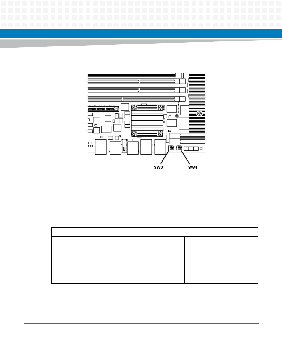
Page 35: Figure 2-3, Switch location with heat sink sw3 and sw4, Setup
Advertising
Setup
ATCA-9405 Installation and Use (6806800M71G)
35
2.3.1.1
FPGA and CPLD/IPMC Switches
The switch settings are described in
Figure 2-3
Switch Location with Heat Sink SW3 and SW4
Table 2-3 Settings for Switch SW1
Switch
Description
Default
SW1-1
IPMI Boot Select
OFF = SPI Boot Flash is selected by IPMC
ON = SPI Boot Flash is selected by SW1-2
OFF Default
or
Recovery
SPI
Boot
Flash
is selected by IPMC
SW1-2
Manual Boot Select
OFF = Default SPI Boot Flash selected
ON = Recovery SPI Boot Flash selected
OFF
Default SPI Boot Flash is used
Advertising
This manual is related to the following products: