Controls, leds, and connectors, 1 overview, 2 seeprom address switch, s1 – Artesyn MVME721x RTM Installation and Use (April 2015) User Manual
Page 39: 1 overview 3.2 seeprom address switch, s1, Table 3-1, Seeprom address switch assignments (rtm), Table 3-2, Switch settings and device addresses, Figure 3-1, S1 switch positions
Advertising
Chapter 3
MVME721X RTM Installation and Use (6806800M42D)
39
Controls, LEDs, and Connectors
3.1
Overview
This chapter describes:
SEEPROM Address Switch, S1
Rear Panel Connectors and LEDs
FRU Serial EEPROM
3.2
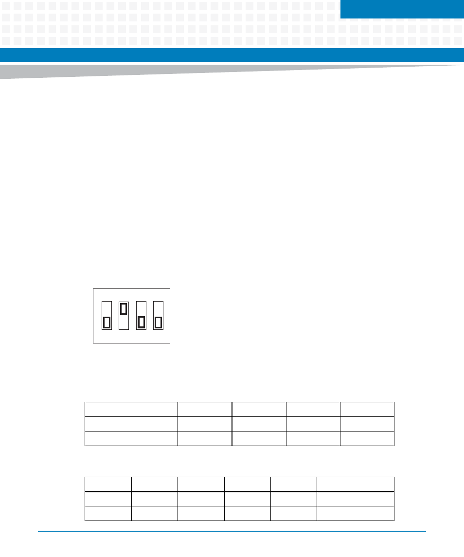
SEEPROM Address Switch, S1
A 4-position SMT configuration switch is located on the MVME721X RTM to set the device
address of the RTM serial EEPROM device. The switch settings are defined in the next table.
Figure 3-1
S1 Switch Positions
Table 3-1 SEEPROM Address Switch Assignments (RTM)
Position
SW4
SW3
SW2
SW1
Function
WP
A(2)
A(1)
A(0)
Default (OFF)
0
1
1
1
Table 3-2 Switch Settings and Device Addresses
SW4
SW3
SW2
SW1
A(2-0)
Device Address
OFF
ON
ON
ON
000
$A0
OFF
ON
ON
OFF
001
$A2
ON
1
2
3
4
Advertising