2 leds, Table 3-8, Front panel leds – Artesyn MVME721x RTM Installation and Use (April 2015) User Manual
Page 48: Controls, leds, and connectors
Controls, LEDs, and Connectors
MVME721X RTM Installation and Use (6806800M42D)
48
3.3.2
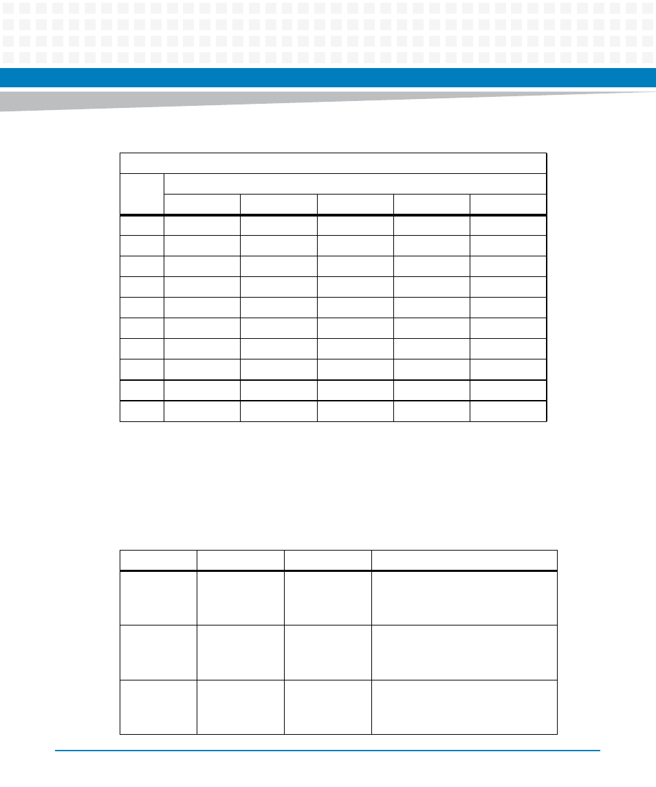
LEDs
There are two sets of ACT and SPEED LEDs, one set for each Ethernet connector. They are
described in the next table. For LED positions, please see
23
PMC IO 46
NC
PMC IO 45
E2_3 -
Serial 3 RTS
24
PMC IO 48
NC
PMC IO 47
E2_3+
GND
25
PMC IO 50
NC
PMC IO 49
GND
Serial 4 RX
26
PMC IO 52
NC
PMC IO 51
E2_2 -
GND
27
PMC IO 54
NC
PMC IO 53
E2_2 +
Serial 4 TX
28
PMC IO 56
NC
PMC IO 55
GND
GND
29
PMC IO 58
NC
PMC IO 57
E2_1 -
Serial 4 CTS
30
PMC IO 60
NC
PMC IO 59
E2_2 +
GND
31
PMC IO 62
GND
PMC IO 61
GND
Serial 4 RTS
32
PMC IO 64
+5V
PMC IO 63
+5V
GND
Table 3-7 VME Backplane P2 Connector Pin Assignments (continued)
P2 Connector
Pin
Name
Signal Description
Row A
Row B
Row C
Row D
Row Z
Table 3-8 Front Panel LEDs
Label
Location
Color
Description
GENET1
SPEED
Front panel
Integrated
RJ45 LED
Off
Amber
Green
No link
10/100BASE-T operation
1000 BASE-T operation
GENET1
ACT
Front panel
Integrated
RJ45 LED
Off
Blinking Green
No activity
Activity proportional to bandwidth
utilization
GENET2
SPEED
Front panel
Integrated RJ45
LED (Left)
Off
Amber
Green
No link
10/100BASE-T operation
1000BASE-T operation