1 rear panel connectors, 1 j1 (serial) and j2 (ethernet) pinout connectors, Table 3-3 – Artesyn MVME721x RTM Installation and Use (April 2015) User Manual
Page 42: Transition module connectors, Table 3-4, J1 and j2 connector pin assignments, J1 (serial) and j2 (ethernet) pinout, Connectors, Chapter 3, rear panel connectors, Controls, leds, and connectors
Controls, LEDs, and Connectors
MVME721X RTM Installation and Use (6806800M42D)
42
3.3.1
Rear Panel Connectors
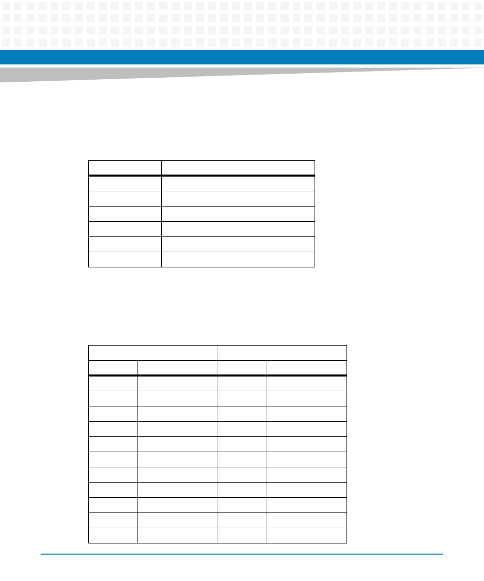
All connectors use standard pin assignments in compliance with the VMEbus specifications:
3.3.1.1
J1 (Serial) and J2 (Ethernet) Pinout Connectors
The pin assignments for the J1 and J2 connectors are as follows:
Table 3-3 Transition Module Connectors
Connector
Function
J1A, J1B, J1C, J1D
COM port connectors
J2A
10/100/1000Mb/s Ethernet connector
J2B
10/100/1000Mb/s Ethernet connector
J10
PIM power/ground
J14
PIM I/O
P2
VME backplane connector
Table 3-4 J1 and J2 Connector Pin Assignments
J1
J2
Pin Name
Signal Description
Pin Name
Signal Description
A1
NC
A1
E2_0P
A2
SP4_RTS
A2
E2_0N
A3
GND
A3
E2_1P
A4
SP4_TX
A4
E2_1N
A5
SP4_RX
A5
E2_2P
A6
GND
A6
E2_2N
A7
SP4_CTS
A7
E2_3P
A8
NC
A8
E2_3N
B1
NC
B1
E1_0P
B2
SP3_RTS
B2
E1_0N
B3
GND
B3
E1_1P