4 board thermal management and placement, Figure 2-1, Board thermal management diagram – Artesyn NITX-315/NITX-315-ET Installation and Use (August 2014) User Manual
Page 34: Figure "board thermal management
Hardware Preparation and Installation
NITX-315/NITX-315-ET Installation and Use (6806800L71D)
34
Prepare the parts and the tools
Prepare the components to be installed or replaced.
When you hold or transport the components, use the special antistatic package. Prepare
the cross screwdriver, screws, plastic supports, cooling gel, and ESD-preventive wrist
strap.
Confirm installation or changing position
Confirm the position where NITX-315/NITX-315-ET will be installed.
If a serious problem occurs and cannot be solved when you install or replace the
component, contact Artesyn Embedded Technologies for technical support.
2.4
Board Thermal Management and Placement
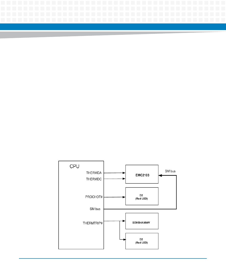
NITX-315/NITX-315-ET provides a thermal management strategy. This includes CPU junction
temperature monitoring, one on-board fan connector, and can take the corresponding action
to protect the system during catastrophic overheating.
The following diagram shows thermal management strategy:
Figure 2-1
Board Thermal Management Diagram