Commlink 5 technical guide, Connections and wiring, 5 operator interface – Auto-Zone Control Systems CommLink 5 Technical Guide, Installation Instructions for the CommLink 5 Communications Interface (Version 01G) User Manual
Page 5: Commlink 5 connections & wiring, Figure 1: commlink 5 connection & wiring
CommLink 5 Technical Guide
5
Operator Interface
Connections and Wiring
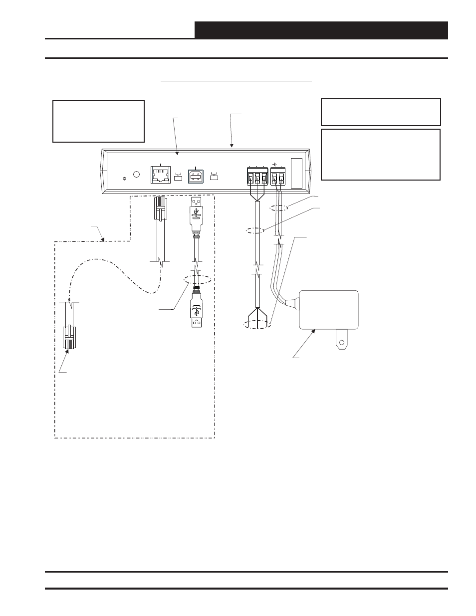
Figure 1: CommLink 5 Connection & Wiring
24 VAC Power
If Desired A 24 VAC Transformer
Rated At 12 VA Minimum May Be
Used Instead Of The Supplied Power Pack.
Use 18 Gauge Minimum 2 Conductor Wire
Between The Transformer & CommLink 5
Terminals
(Not
Included)
120 to 24 VAC Power Pack
(Included) Connect To 120/1/60
Duplex Receptacle (By Others)
USB Cable (Included).
Connect This Cable To
Your Computer USB Port
For Direct Connection To
The CommLink 5. Also
Used For Advanced
Configuration of The
CommLink 5.
CommLink 5
Communications
Interface
CommLink 5 Connections & Wiring
NOTES:
1) Use 18 Gauge Minimum 2 Conductor Twisted Pair With Shield Cable Belden #82760 Or Equivalent (Not Included) To Connect
The CommLink 5 To A MiniLink or MiniLink PD.
2) For Direct Connection Via USB, Your Computer Must Have An Unused USB Port Available. Drivers For Your USB Port Are
Provided On A CD Supplied With The CommLink 5. Please Follow The Directions In The CommLink 5 USB Driver Installation
Section (Included) To Install And Configure The USB Drivers.
3) The CommLink 5 Cannot Communicate With The Control System Through Its Ethernet Port And USB Port At The Same Time.
4) All Wiring Must Conform To Applicable Federal, State & Local Electrical Wiring Codes.
18 Gauge 2 Conductor
With Shield (Not Included)
See Note 1
Connect To A
MiniLink PD, MiniLink
Or Other Controller As
Required By Your
Specific System
Wiring Instructions.
See Note 1
Serial #
COMPUTER
USB
10/100
ETHERNET
DIAG
485 LOOP POWER
ACT
LNK
Optional Items
Not Required
For CommLink-Only
Installations.
When Using
A MiniLink,
Switch Should
Be Set To
Multiple.
HIGH
LOW
BAUD
R(
+
)
24V
GND
SH
LD
T(
-)
MUL
T
IPLE
SINGLE
LOOP
WARNING! If You Are Using The IP
Module With Your CommLink, Do Not
Have Your Ethernet Connection And
USB Connection Connected At The
Same Time. This Could Cause
Unreliable Communications.
Optional - Prefabricated
Ft. Long CAT5
Ethernet Cable (Included With Optional OE415-
02 IP Module Kit).
If A Longer
Ethernet Cable Is Required, You Will Need To
Obtain (From Others) And Install An Ethernet
Cable Of The Required Length For Your
Installation.
10
Connect To A 10/100 Base-T
Ethernet Router On Your LAN.
WARNING! If You Are Replacing An Earlier
Version Of The CommLink With A CommLink 5,
Be Aware That The Polarity Of The Terminal
Block Is Reversed On The CommLink 5 From
All Previous Models. You Must Always Confirm
That The Polarity Is Correct When Wiring 24 VAC
Power To The CommLink Power Terminal Block
Or Serious Damage To The Product Will Result.
NOTE: Please Note, The R(+) And T(-) Terminals
On The Communications Terminal Block Are
Reversed From All Previous Versions Of The
CommLink.
Revised: 11/06/12