Howtorfid – Avery Dennison RFID User Manual
Page 12
HowToRFID
Revision: 13
Date: 31 August 2009
Page 12 of 53
Printer
PH-CT [mm]
PH-TB [mm]
PH-CA [mm]
PH-DE [mm]
MBF [mm]
64-0X
17.13
10.50
62.00
48.50
AP 5.4
17.00
10.00
46.50
16
ALX 92x / DPM
n/a
n/a
50.00
24.20 (short
dispensing
edge)
39.80 (long
dispensing
edge)
ca. 100
Table 3 –Paper path dimensions of printer relevant for RFID
2.4.3
Inlay position / Tag antenna coupling
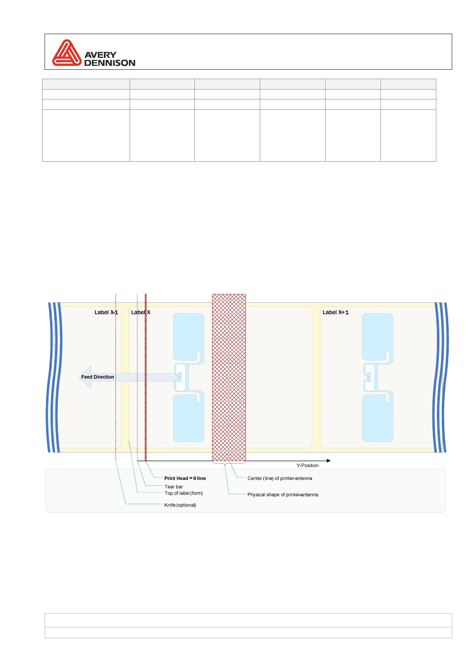
Smart labels with RFID functionality are treated by the printer in a
two phase process. At first RFID functionality is
executed and afterwards the regular print processing is made. To communicate with an RFID transponder it has to
be in the range (RF field) of the built in reader antenna and it must be the only tag in range. For this purpose the
Easy Plug command #IM has been extended with a parameter called
RFID antenna offset. It defines the distance
between label start and optimal coupling point position. In other words, it determines how much the label needs to
be back feed to bring the transponder in the right position near the printer’s antenna.
Figure 2: positioning at label start