Module-specific register description – BECKHOFF KL2521-0000 User Manual
Page 14
Access from the user program
12
KL2521
Module-specific register description
R7:
Command register [0x0000]
For a standard command to be executed, it is first necessary for the user
code word, 0x1235, to be entered into
register R31
.
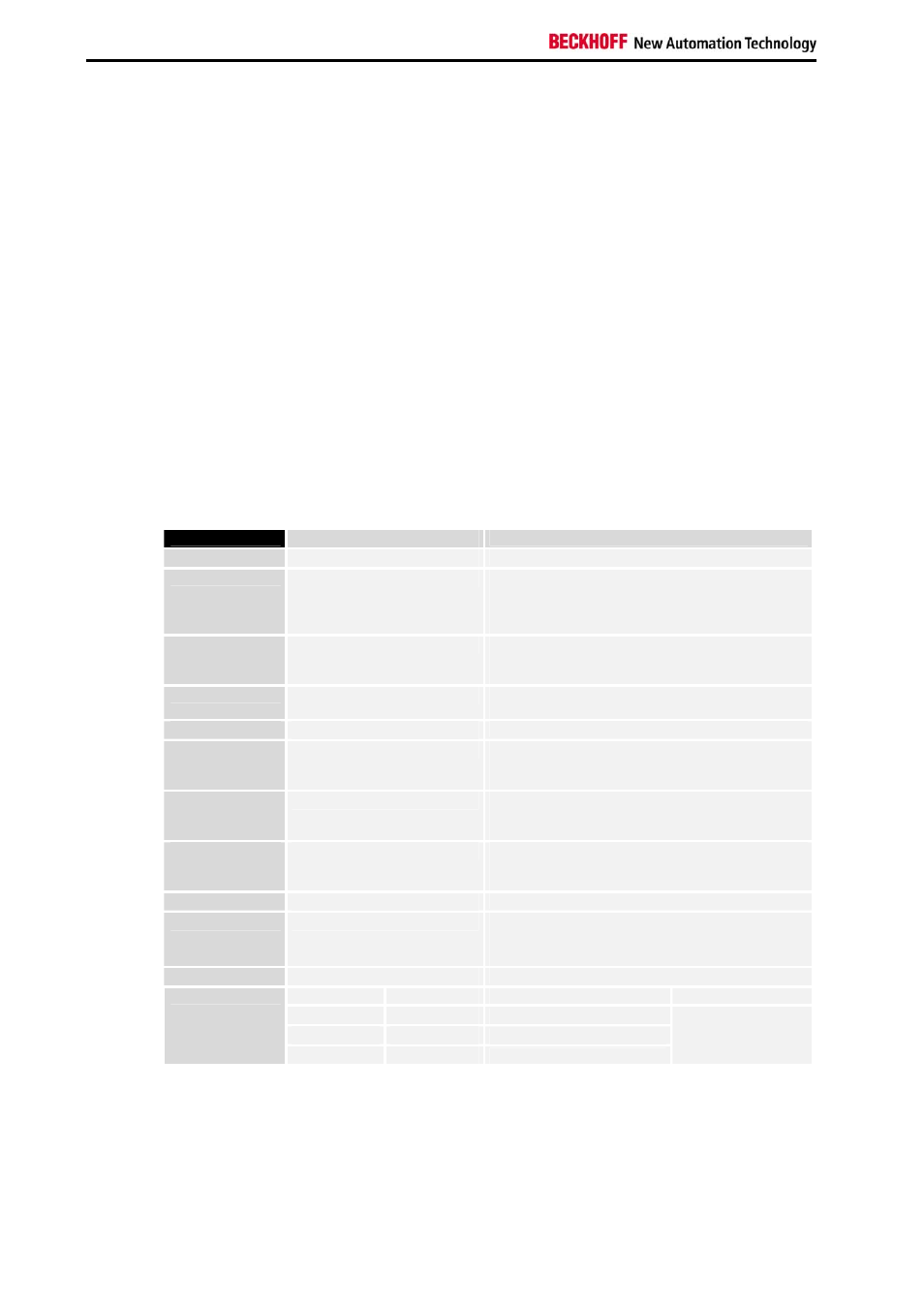
Command 0x7000: Restore Factory Settings
Entering 0x7000 in register R7 restores the factory settings for the
following registers:
R32:
R33:
R34:
R35:
R36:
R37:
0x0030
0x0000
0x0000
0x0000
0xC350
0x0000
(48
dec
)
(0
dec
)
(0
dec
)
(0
dec
)
(50000
dec
)
(0
dec
)
R38:
R39:
R40:
R41:
R42:
R43:
0x86A0
0x0001
0x03E8
0x03E8
0x0064
0x0032
(34464
dec
)
(1
dec
)
(1000
dec
)
(1000
dec
)
(100
dec
)
(50
dec
)
R32:
Feature register [0x0030]
The feature register specifies the terminal’s operating mode.
Feature bit no.
Description of the operating mode
Bit 1 – Bit 0
-
No function
Bit 2
0
[0] Watchdog timer active
The watchdog timer is switched on by default.
Either the manufacturer's of the user's switch-on
value is output if the watchdog overflows.
Bit 3
1
[0] Sign / amount representation [0]
Sign / amount representation is active instead of
two's-complement representation. (-1 = 0x8001)
Bit 4
1
[1] The counter is cleared by a rising edge in the
Counter_Clear bit in the control byte
Bit 5
1
[1] Ramp function active
Bit 6
0/1
[0] Ramp base frequency
0: 10 Hz/s
1: 1000 Hz/s
Bit 7
0/1
[0] Input mode
0: relative
1: direct
Bit 8
0/1
[0] Behavior when watchdog triggered
0: Manufacturer's switch-on value
1: User's switch-on value
Bit 9
1
[0] Travel distance control active
Bit 10
0/1
[0] Counter
0: delete
1: set
Bit 12 – Bit 11
-
No function
pos. logic
neg. logic
[000] Operating mode
Value range
000
100
Frequency modulation
001
101
Pulse-direction control
Bit 15 – Bit 13
010
110
Incremental encoder
0 – 500 kHz