Output pattern, Led display – BECKHOFF KL2521-0000 User Manual
Page 8
Functional description
6
KL2521
Output pattern
operating modes
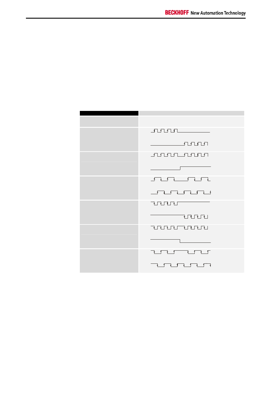
The pattern of pulses is output through channels A and B. It is possible to
configure the necessary operating mode via feature register R32.
The operating modes differ primarily between the positive logic modes 0, 1
and 2 and the negative logic modes 4, 5 and 6.
Operating modes 2 and 6 simulate an incremental encoder, and permit
direct connection to an evaluation unit such as a servoamplifier or
frequency converter with an incremental encoder input.
Operating mode
Function
Rotation to the right Rotation to the left
Frequency modulation
positive logic ( BA 0 )
A
B
Pulse-direction control
positive logic ( BA 1 )
A
B
Incremental encoder
positive logic ( BA 2 )
A
B
Frequency modulation
negative logic ( BA 4 )
A
B
Pulse-direction control
negative logic ( BA 5 )
A
B
Incremental encoder
negative logic ( BA 6 )
A
B
LED display
Signal
LEDs
The 4 LEDs illuminate when the input and output signal levels are active.
The illumination of the LEDs for the active frequency outputs A or B at
higher frequencies can only be perceived as a glow at half brightness.
watchdog
When the watchdog is active (Feature.2 = 0!) the terminal will switch the
outputs off or will output a value stored in register 35 if no new process
data is transferred to the terminal within 100 ms.