Register description, General description of registers – BECKHOFF KL3311 User Manual
Page 11
Register Description
KL3311, KL3312, KL3314 and KL3302
9
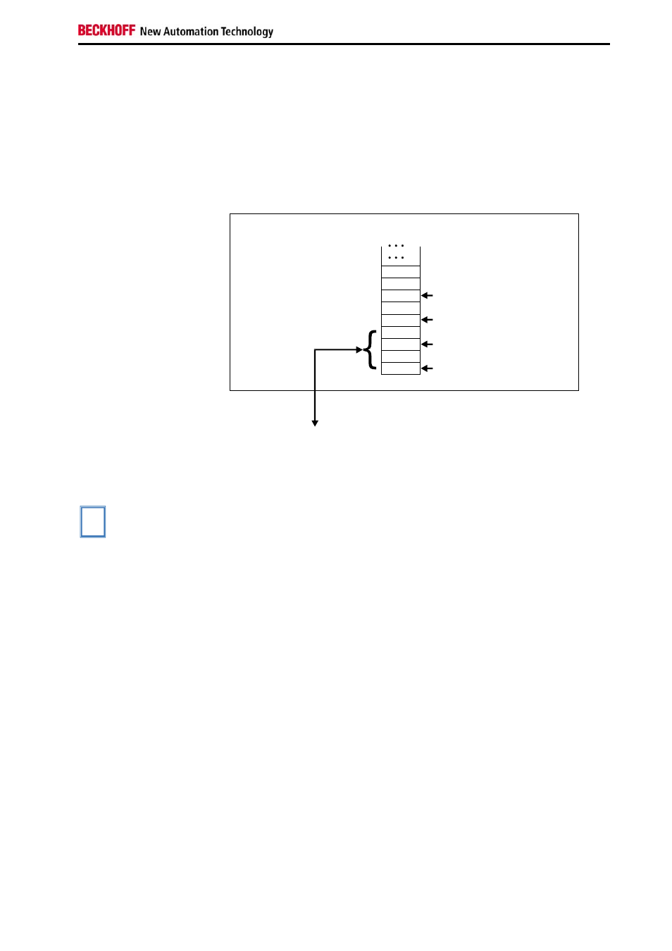
BK4000 Interbus Coupler
The BK4000 Interbus Coupler maps the terminals in the delivery state with
2 bytes per channel:
• KL3311: 2 bytes of input data
• KL3312 (KL3302): 4 bytes of input data
• KL3314: 8 bytes of input data
Parameterization via the fieldbus is not possible. If the control and status
byte is to be used, the KS2000 configuration software is required.
Example for KL3312 (KL3302):
Offset Terminal1 Channel1 = 0
Offset Terminal2 Channel1 = 4
Offset Terminal1 Channel2 = 2
Offset Terminal2 Channel1 = 6
The control/status byte
must be inserted for
parameterization (KS2000).
K-Bus
Interbus bus coupler
BK4000
To the bus terminal
D0 - 1
D0 - 0
Data H
Data H
Data H
D1 - 0
D1 - 1
Data L
Data L
0
The terminal is
mapped in the
bus coupler.
Other Bus Couplers and
further information
Further information about the mapping configuration of Bus Couplers can
be found in the Appendix of the respective Bus Coupler manual under
Master configuration.
i
Note
The Appendix contains an overview of possible mapping configurations
depending on the parameters that can be set.
Parameterization with
KS2000
The parameterizations can be carried out independently of the fieldbus
system with the KS2000 configuration software via the serial configuration
interface in the Bus Coupler.
Register Description
Different operating modes or functionalities may be set for the complex
terminals. The General Description of Registers explains those register
contents that are the same for all complex terminals.
The terminal-specific registers are explained in the following section.
Access to the internal terminal registers is described in the Register
Communication section.
General Description of Registers
Complex terminals that possess a processor are able to exchange data bi-
directionally with the higher-level controller. These terminals are referred to
below as intelligent Bus Terminals. These include analog inputs, analog
outputs, serial interface terminals (RS485, RS232, TTY etc.), counter
terminals, encoder interface, SSI interface, PWM terminal and all other
parameterizable terminals.