Functional description – BECKHOFF KL3311 User Manual
Page 7
Functional description
KL3311, KL3312, KL3314 and KL3302
5
Functional description
The thermocouple terminals KL3311, KL3302 (without broken wire
detection), KL3312 and KL3314 can evaluate type J, K, B, E, N, R, S, T, U
and L thermocouples. The characteristic curves are linearized and the
reference temperature determined directly within the terminal.
Temperatures are output in 1/10°C. The terminal is fully configurable via
the Bus Coupler or the control. Different output formats may be selected or
own scaling activated. In addition, linearization of the characteristic curve
and determination and calculation of the reference temperature
(temperature at the terminal connection contacts) can be switched off.
Functioning
Thermocouples can be classified as active measuring sensors. They
exploit the thermo-electric effect (Seebeck, Peltier, Thomson). Where two
electrical conductors of different materials (e.g. iron and constantan) make
contact, charge is transferred across the contact surface. A contact
potential develops, and is strongly dependent on temperature. The
thermally generated voltage is both a function of the temperature being
measured, T, and of the reference temperature, T
v
, at the point where
contact is made with the thermocouple. Since the coefficients are
determined at a reference temperature of 0°C, it is necessary to
compensate for the effect of the reference temperature. This is done by
converting the reference temperature into a reference voltage that depends
on the type of thermocouple, and adding this to the measured thermal
voltage. The temperature is found from the resulting voltage and the
corresponding curve.
U
k
= U
meas
+ U
ref
T
aus
= f(U
k
)
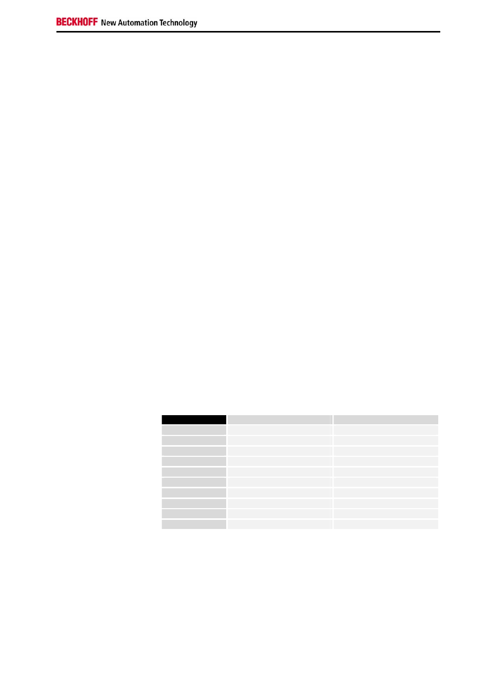
Process data output format In the delivery state, the measured value is displayed in increments of
1/10 °C in two's complement format (integer). Other display types can be
selected via the feature register (e.g. sign/amount representation, Siemens
output format).
Measured value
Hexadecimal output
Signed integer output
-200.0°C
0xF830
-2000
-100.0°C
0xFC18
-1000
-0.1°C
0xFFFF
-1
0.0°C
0x0000
0
0.1°C
0x0001
1
100.0°C
0x03E8
1000
200.0°C
0x07D0
2000
500.0°C
0x1388
5000
850.0°C
0x2134
8500
1,000.0°C
0x2710
10000
Voltage limits
U
k
> U
kmax
: Bits 1 and 6 (over range and error bits) in the status byte are
set. The linearization of the characteristic curve is continued with the
coefficients of the upper range limit up to the limit stop of the A/D converter
or to the maximum value of 0x7FFF.