BECKHOFF KL6071 User Manual
Page 10
Terminal configuration
8
KL6071
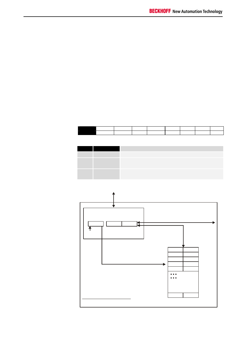
3.4 Register communication with KL6071
Register access via
process data transfer
Bit 7=1: register mode
When bit 7 of the control byte is set, the first two bytes of the user data are
not used for process data transfer, but are written into or read out of the
terminal’s register.
Bit 6=0: read
Bit 6=1: write
In bit 6 of the control byte, you define whether a register is to be read or
written. When bit 6 is not set, a register is read without modification. The
value can be taken from the input process image.
When bit 6 is set, the user data is written into a register. The operation is
concluded as soon as the status byte in the input process image has
supplied an acknowledgement (see examples).
Bits 0 to 5: address
The address of the register to be addressed is entered in bits 0 to 5 of the
control byte.
Control byte in the register mode
Bit
7
6
5
4
3
2
1
0
Name
REG=1
W/R
A5
A4
A3
A2
A1
A0
Key
Bit
Name
Comment
7
REG
1 for access to register structure
6
W/R0
0: Read register
1: Write register
5-0
A5...A0
A total of 64 registers can be addressed with the
addresses A5...A0
0
63
Terminal´s
register set
64 words
Control-/
status byte
User data
K-Bus
If control bit 7=0: input/output
If control bit 7=1:
register-
configuration
C/S-bit 7
If control bit 7=1:
adress in the control bit 0-5
If control bit 6=0: read
If control bit 6=1: write
Complex bus terminal
To the bus coupler
H
H
L
L
2 or mors bytes
The control or status byte occupies the lowest address of a logical channel.
The corresponding register values are located in the following 2 data bytes
(the BK2000 is an exception to the rule: here, an unused data byte is
inserted after the control or status byte, thus setting the register value to a
word limit).