BECKHOFF KL6071 User Manual
Page 7
Terminal configuration
KL6071
5
R8: Terminal type:
The terminal type in register R8 is needed to identify the terminal.
R9: Firmware version X.y
The firmware version can be read as an ASCII character string.
3.2.1.1
R10: Data length
R10 contains the number of multiplexed shift registers and their length in
bits.
The bus coupler sees this structure.
R11: Signal channels
In comparison with R10, the number of logically existing channels is
located here. For example, one physically existing shift register may
consist of several signal channels.
R12: Minimum data length
The respective byte contains the minimum data length of a channel to be
transferred. If the MSB is set, then the control/status byte is not necessarily
needed for the function of the terminal and, with appropriate configuration
of the coupler, is not transferred to the control system.
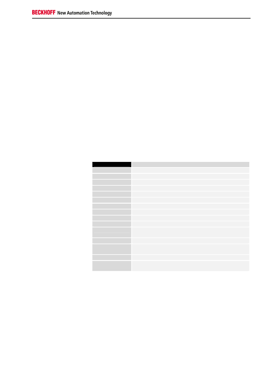
R13: Data type register
Data type
register
0x00
Terminal without valid data type
0x01
Byte array
0x02
1 byte n bytes structure
0x03
Word array
0x04
1 byte n words structure
0x05
Double word array
0x06
1 byte n double words structure
0x07
1 byte 1 double word structure
0x08
1 byte 1 double word structure
0x11
Byte-array with a variable logical channel length
0x12
1 byte n bytes structure with a variable logical channel
length (eg 60xx)
0x13
Word-array with a variable logical channel length
0x14
1 byte n words structure with a variable logical channel
length
0x15
Double word array with a variable logical channel length
0x16
1 byte n double words structure with a variable logical
channel length
R14: not used
R15: Alignment bits (RAM)
The analog terminal is set to a byte limit in the terminal bus with the
alignment bits.
Manufacturer parameters
R16 to R30: Manufacturer parameter area (SEEROM)
The manufacturer parameters are specific to each terminal type. They are
programmed by the manufacturer but can also be modified from the control
system. The manufacturer parameters are stored permanently in a serial
EEPROM and are therefore not destroyed by power failures.
These registers can only be modified after setting a code word in R31.