BECKHOFF EP1908 User Manual
Page 19
Operation
EP1908-0002
17
4.1.5.5
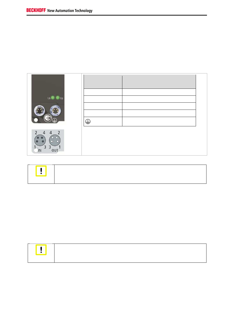
Power Connection
Two M8 connectors at the low-end of the modules are used for feeding and routing the supply voltages:
•
IN: left M8 connector for feeding the supply voltages
•
OUT: right M8 connector for routing the supply voltages
•
Earthing screw: The earthing screw is installed in the factory. An additional M3 ring cable lug and
the earthing cable are required for the installation.
Pin assignment
Contact
Voltage
1
Control voltage Us, +24 V
DC
2
Peripheral voltage Up, +24 V
DC
3
GND
S
4
GND
P
Earthing connection
The contacts of the M8 plug connectors can conduct a maximum
current of 4 A.
Two LEDs indicate the status of the supply voltages.
Attention
Do not confuse the power port with EtherCAT port!
Never connect the power cables (M8, 24 V
DC
) to the green-marked EtherCAT sockets
of the EtherCAT Box Modules. This can cause the destruction of the modules!
Control voltage U
S
: 24V
DC
The control voltage U
S
supplies the logic and communication parts of the module. It is galvanically
isolated from the fieldbus part.
Peripheral voltage U
P
: 24V
DC
The peripheral voltage U
p
supplies the digital inputs; it can be brought in separately. If the load voltage is
switched off, the fieldbus function is preserved, but the input signals switch to safe state.
Redirection of the supply voltages
The power IN and OUT connections are bridged in the module. Hence, the supply voltages U
s
and U
p
can
be passed from EtherCAT Box to EtherCAT Box in a simple manner.
Attention
Note the maximum current!
Ensure that the maximum permitted current of 4 A for the M8 plug connectors is not
exceeded when routing the supply voltages U
S
and U
P
!