2 hardware, 1 fc1100 | pci ethercat slave card, 2 fc1121 | pcie ethercat slave card – BECKHOFF FC1100 User Manual
Page 8: Hardware, Fc1100 | pci ethercat slave card, Fc1121 | pcie ethercat slave card, Et1100
2
Hardware
The hardware design focused to create an easy communication interface to an EtherCAT network.
The complete local memory area of the ESC (EtherCAT Slave Controller) is mapped to the memory
range of the slave card. In case of the FC1100 the AL Event Interrupt is mapped to the PCI bus on
interrupt line INTA.
2.1
FC1100 | PCI EtherCAT slave card
The PCI ID values of the FC1100 are listed in Table 2. The ET1100 (see type and revision register for
detailed information) chip is used to access the EtherCAT network. The address range of the ET1100
is mapped to the memory specified by Base Address Registers 2 (BAR2) of the PCI device.
NOTE: The low nibble of BAR2 contains configuration bits
The AL Event (PDI IRQ) is mapped to INTA of the PCI bus.
Table 2: FC1100 PCI values
Parameter
Value
DeviceID
0x1100
VendorID
0x15ec
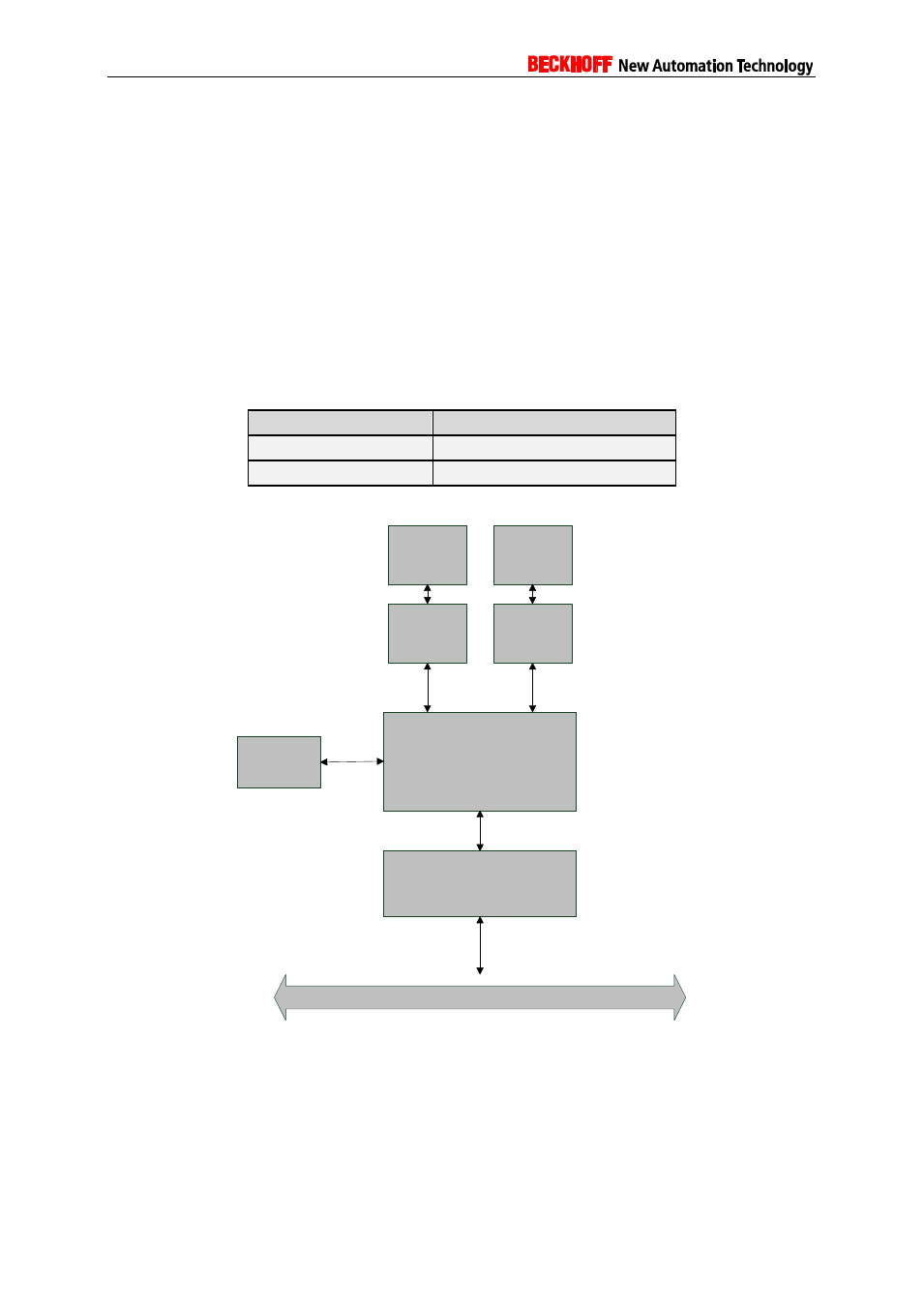
Figure 1 shows the hardware structure of the FC1100 slave card.
PLX
(PCI 9030)
ET1100
EEPROM
System PCI Bus
MII
I²C
16bit
µC Interface
MII
Connector/
Magnestics
PHY
Connector/
Magnestics
PHY
Figure 1: Hardware Schema
2.2
FC1121 | PCIe EtherCAT slave card
The PCIe ID values of the FC1121 are listed in Table 3. An FPGA based EtherCAT Slave Controller
(ESC) is used to access the EtherCAT network. For ESC specific information (e.g. type and revision)
see the corresponding ESC registers readout by an EtherCAT master or configuration tool.
The address range of the IPCore need to be determined by the information and function description
located at the beginning of BAR0 (Figure 2: FC1121 BAR0 memory mapping). The address is BAR0
plus the offset specified in the EtherCAT slave function block (Function type 0x0002).