8 indicators and switches, 1 start-up procedure and diagnostics leds – BECKHOFF ILxxxx-B520 User Manual
Page 34
Indicators and Switches
31
ILxxxx-B520
8 Indicators and Switches
8.1 Start-up procedure and Diagnostics LEDs
Start-up procedure and
Diagnostic
After switching on, the ILxxxx-B520 immediately checks the connected
configuration. Error-free start-up is signalled by the red "I/O ERR“ LED
being extinguished. If the “I/O ERR” LED blinks, an error in the area of the
extension boxes is indicated. The error code can be determined from the
frequency and number of blinks. This permits rapid rectification of the error.
There is a detailed description in the section on "The diagnostic LEDs".
The diagnostic LEDs
The ILxxxx-B520 has two groups of LEDs for the display of status. The
upper group with two LEDs indicates the status of the respective fieldbus.
The significance of the “fieldbus status“ LED is explained in the relevant
sections of this manual - it conforms to conventional fieldbus displays.
On the bottom of the ILxxxx-B520 are two more green LEDs that indicate
the supply voltage. The left hand LED indicates the presence of the 24 V
supply for the ILxxxx-B520. The right hand LED indicates the presence of
the supply to the power contacts.
Local errors
Two LEDs, the “I/O LEDs”, in the area below the field bus status LEDs
referred to above, serve to indicate the operating status of the ILxxxx-B520
and the connected extension boxes. The green LED lights up in order to
indicate fault-free operation. The red LED blinks with two different frequen-
cies in order to indicate an error. The error is encoded in the blinks as fol-
lows:
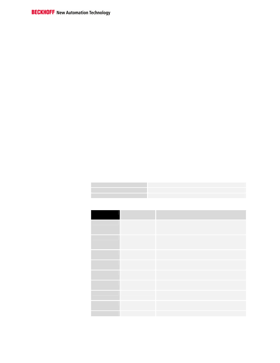
Fast blinking
Start of the error code
First slow sequence
Error code
Blink code
Second slow sequence
Error code argument
Error location
Error code
Error code ar-
gument
Description
1 pulse
0
1
2
EEPROM checksum error
Inline code buffer overflow
Unknown data type
2 pulses
0
n (n > 0)
Programmed configuration
Incorrect table entry / Ilxxxx-B520
Incorrect table comparison (extension box n)
3 pulses
0
n
Interruption of IP-Link bus
Break behind extension box (0: ILxxxx-B520)
4 pulses
0
n
IP-Link bus data error (incorrect telegram)
Extension box n (0: Ilxxxx-B520)
5 pulses
n
IP-Link bus error in register communication with
extension box n
6 pulses
0
n (n > 0)
Special fieldbus error
11 pulses
n
IR Error, no communication, extension box n is
not processing the IR commands
12 pulses
n
More than 120 extension boxes
n extension boxes too much
13 pulses
n
unknown box type, extension box n
The number of pulses in the first sequence indicates the error type, while