Dc link diagram – BECKHOFF AL2000 Application User Manual
Page 38
Advertising
Eiserstraße 5 / D-33415 Verl / Telefon 05246/963-0 / Telefax 05246/963-149
38
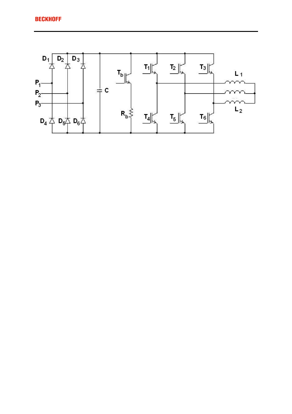
DC link diagram
P1, P2 and P3: the three phases of the AC power supply.
• D1 ... D6: these diodes are part of the 3 phase diode bridge.
• C: the DC link capacitor.
• Tb: the activating transistor of the braking resistor.
• Rb: the braking resistor.
• T1 ... T6: transistors of the PWM amplifier stage.
• L1, L2 and L3: The coils of the motor.
Advertising
See also other documents in the category BECKHOFF Equipment:
- Bus Terminal System (19 pages)
- EP-xxxx-xxxx (19 pages)
- BK2000 (30 pages)
- LC3100 (67 pages)
- BK4000 (28 pages)
- BK3xx0 (95 pages)
- BK5000 (12 pages)
- LC5200 (32 pages)
- BK7000 (29 pages)
- BK7500 (32 pages)
- BK7300 (40 pages)
- BK8100 (26 pages)
- BC2000 (28 pages)
- BC3100 (51 pages)
- BC7300 (48 pages)
- BC8100 (36 pages)
- BC3150 (112 pages)
- KL1012 (2 pages)
- KL1114 (2 pages)
- KL1164 (1 page)
- KL1232-xxxx (4 pages)
- KL1501 (19 pages)
- KL1512 (15 pages)
- KL2521-0024 (18 pages)
- KL2512 (21 pages)
- KL2612 (4 pages)
- KL2622 (9 pages)
- KL3062 (24 pages)
- KL3064 (20 pages)
- KL4132 (19 pages)
- KL4034 (25 pages)
- KL3302 (23 pages)
- KL3351 (18 pages)
- KS3681 (43 pages)
- KL4112 (18 pages)
- KL5001 (16 pages)
- KL5051 (17 pages)
- KL5101-0012 (21 pages)
- KS5111-0000 (21 pages)
- KL5121 (19 pages)
- KL6021 (20 pages)
- KL6051 (17 pages)
- Z1000 (2 pages)
- KL6071 (12 pages)
- Z1003 (2 pages)