Soundweb, Control inputs – BSS Audio sw9016 Install Guide User Manual
Page 7
Soundweb 9016 Installation Guide
7
Soundweb
TM
Control Inputs
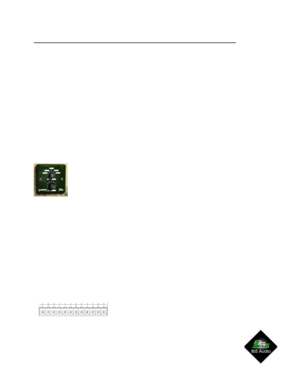
The control ports are designed to be used with a 9012 wall panel or simple switches and
faders or potentiometers. There are four sets of ports, or zones, marked Z1 - Z4. The
control port facilities are used in conjunction with the PC setup software; see its online
help for more details, and for electrical specifications of the 9012 and its resistor values,
see Soundweb Designers online help (under control inputs and logic outputs).
The A pin of any given zone should be connected to a potentiometer for gain control.
The B pin should be connected to a resistor ladder for preset recall/individual
crosspoint control.
The unit is in zone mode when there are no presets loaded. (Note that these are presets
within the unit and nothing to do with Soundweb Designer presets). With each 9012, you
can control the routing of a stereo pair of audio channels and one video channel (a
zone). Up to four 9012s can be connected, so all the outputs can be controlled.
The outputs controlled by each 9012 are dictated by which Z pair of terminals (see
wiring section) they are connected to.
For example, a 9012 plugged into Z1 with the unit in zone mode will:
l
let you control the gain on outputs 1&2 (stereo pair) with the pot
l
let you control the source of the signals routed to audio out 1&2
and video out 1 using the selector switch. With a 9012, this can be
any of the first 5 inputs.
So with the selector in position 2 in the example above:
l
Audio input 5 would be routed to audio output 1.
l
Audio input 6 would be routed to audio output 2.
l
Video input 3 would be routed to video output 1.
The pair of inputs routed to a given output corresponds to the number printed on the
9012 control +1
e.g 0 = inputs 1+2
In preset mode, only the 9012 wall panel connected to Z1 has any effect. The
selector will recall the units five internally installed presets. (again, position 0 on the
selector means preset 1 will be recalled).
Control port pin-outs
Preset/Zone Trigger Inputs
Pin 1 is on right when viewed from rear:
Pin 1, 2, : +5V. Pin 11, 12 : Common
Zone Mode
Pin A Gain, Pin B Source Select
Preset Mode
Use Z1 connections only
Z1 Z2 Z3 Z4
C C A B A B A B A B + +