Soundweb, Rear panel details – BSS Audio sw9010 Install Guide User Manual
Page 5
115
Soundweb
TM
Rear panel details
Network In/Out*
Network In/Out*
Network In/Out*
Network In/Out*
Network In/Out*
Network In - connects to the Network Out socket on another unit. Connecting multiple
units is done in the same way - In to Out.
Refer to the 9088 installation guide and Soundweb Designer help for further details.
The connecting cable is CAT. 5 network cable, terminated with RJ45 connectors, with all
8 cores wired straight through.
Note that the twisted pairs in any CAT.5 network cable must be wired to the following pin
pairs at each terminal:
1 (White-Orange) with 2 (Orange); 3 (White-Green) with 6 (Green);
4 (Blue) with 5 (White-Blue); 7 (White-Brown) with 8 (Brown)
Power/Mic/Logic screw terminal block*
Power/Mic/Logic screw terminal block*
Power/Mic/Logic screw terminal block*
Power/Mic/Logic screw terminal block*
Power/Mic/Logic screw terminal block*
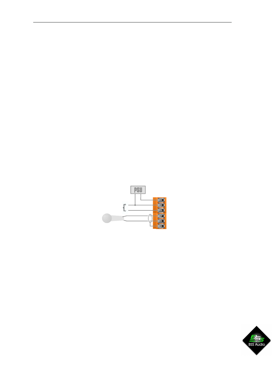
Power In
DC power input (+24V and Gnd). See Power section.
Logic In
Used to connect a switch, (eg: a push-to-talk switch) to the 9010. This input is internally
‘pulled up’ to +5V DC via a 4.7kOhm resistor, so no external voltage source is needed. A
common (ground) connection is provided. A switch may be connected between the input
and common, as shown below.
Mic
_
,+,S
Three connections for an external
dynamic microphone (-,+,S).
PWR GND
+24V In
S
+
-
Logic In
switch
mic.