Soundweb – BSS Audio sw9010 Install Guide User Manual
Page 6
116
Soundweb
TM
Serial Port*
Serial Port*
Serial Port*
Serial Port*
Serial Port*
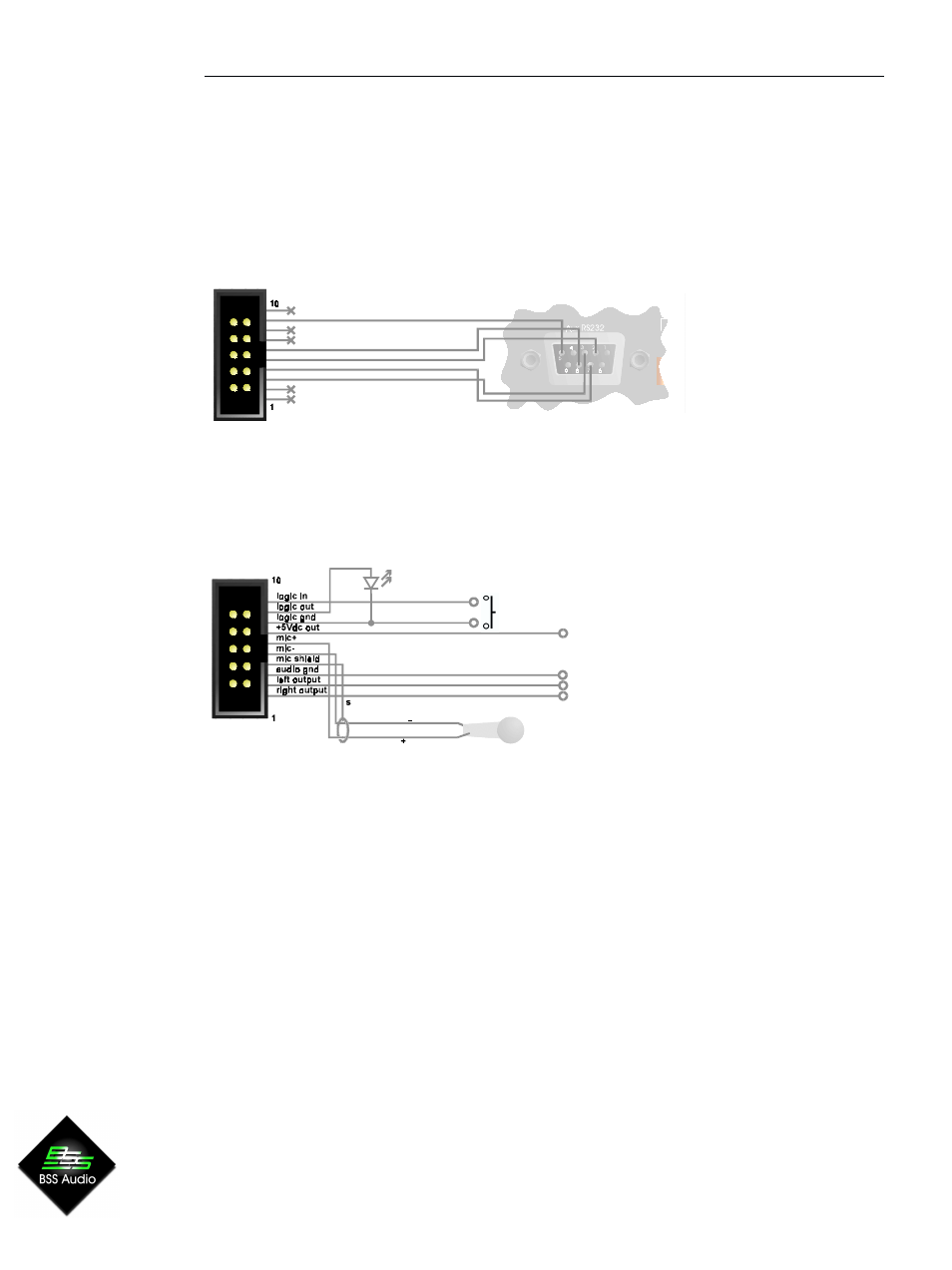
Aux RS232
This is for connection to a PC if required.
The 10-pin header is arranged so that a
standard IDC ribbon cable will pin-out to an IDC D connector for standard PC RS232
connection.
Expansion Port*
Expansion Port*
Expansion Port*
Expansion Port*
Expansion Port*
Left/Right/Audio Gnd output
An unbalanced line-level feed for use in custom applications for monitoring etc. Note that
the outputs are polarity inverted so that external inverting amplifiers may be used. The
signal on these outputs is determined by the Soundweb Designer software.
R out
+5V
switch
Audio GND
L out
Mic
_
,+,S
Commoned to the Mic In terminals on the Power/Mic/Logic screw terminal block.
+5Vdc Out
A low current regulated +5V output for supplying power to electronics for custom
applications. No more than 100mA may be drawn. Current drawn from this output will
impact the length of network cable that may be used between the power supply and the
9010.
*refer to label on back of unit for connection positions.
Logic in
Commoned to the Logic In terminal on the Power/Mic/Logic screw terminal block.
Logic Out
Used to connect the 9010 to a ‘tally’ indicator LED etc. The logic output produces 0V or
+5V DC via an internal 440 Ohm resistor. A common ground connection is provided. An
LED connected between the output (Anode, A) and ground (Cathode, K) will illuminate
when the logic output is activated, without requiring any external current limiting resistor.
Connecting to a power supply
If using the 9010 unit without a 9011 power interface, the network and 9010 should be
connected in the following fashion: