6output details, 7100v line operation, 8bridged mode operation – Cloud Electronics CXA850 User Manual
Page 6: Cxl-40t wired to channel 8, Wiring channels 7 and 8 in bridged mode, 4cx-a850: installation and operation manual, Fig 5, Fig 4
4
CX-A850: Installation and Operation Manual
08-03-05 V4
6
Output Details
Eight 2-pole plug-in screw terminal type connectors (5mm pitch) are provided on the rear
panel for the eight speaker outputs; these can accommodate flexible leads up to 2.50mm².
Do not make any connections to the unit with the power cable attached. It is good practice to
distance the output wiring from the input wiring and keep the speaker wires twisted until they
are terminated to reduce any cross-talk to a minimum level.
7
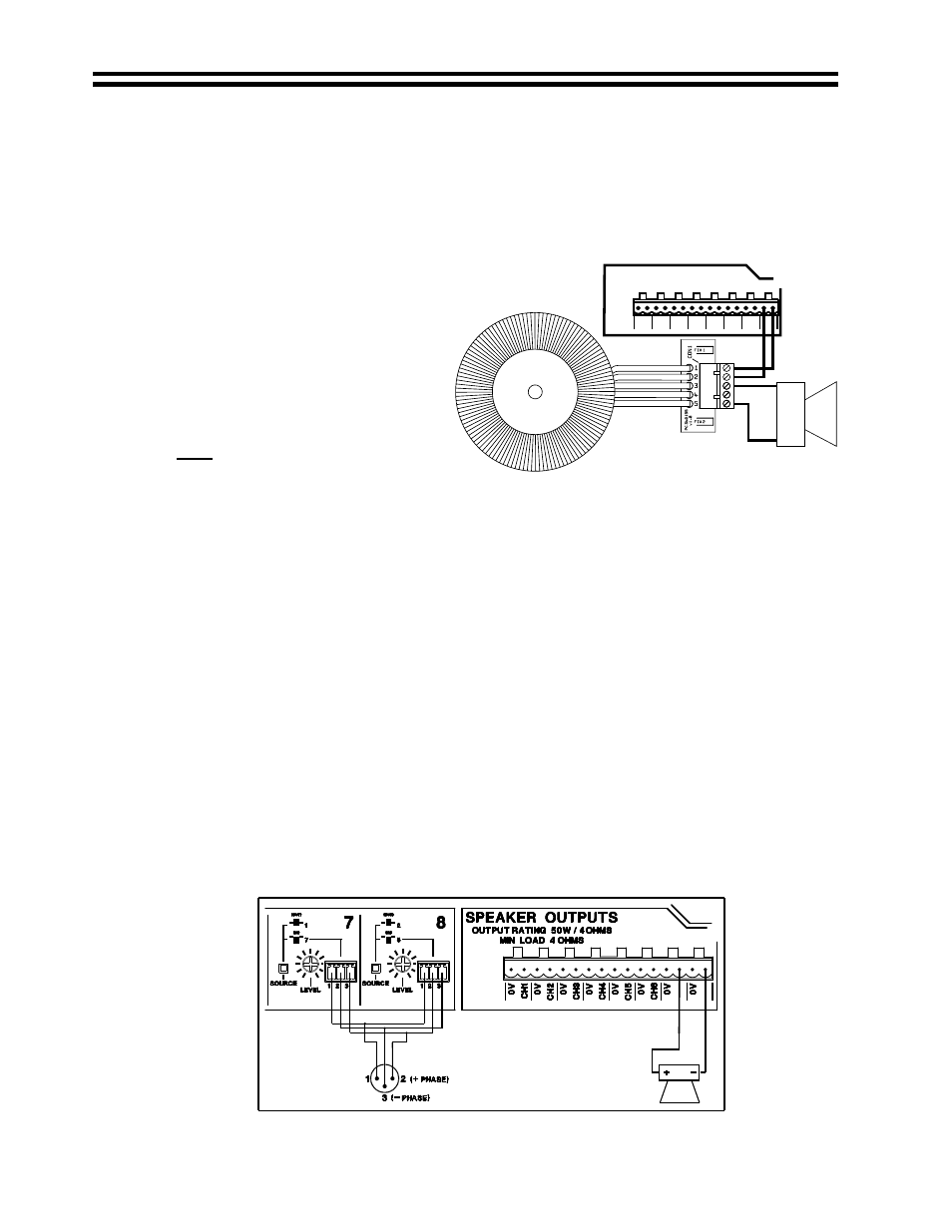
100V Line operation
CXL-40T Wired to Channel 8
An optional single-channel externally
mounted 40W 70V/100V-line
transformer module (CXL-40T) is
available for the CX-A850. The
installer can select 70 or 100V
operation by wiring the speaker
network to the 70V or 100V output
terminals on the CXL-40T. When a
CXL-40T is installed to a zone, the
65Hz high pass filter for that zone
must be switched on using the
appropriate jumper/s. The
instructions below detail the procedure you must follow to activate the appropriate filter
1) Turn the power off & remove the mains lead.
2) Remove the top panel from the unit.
3) Turn the relevant 65Hz high pass filter ‘on’ by moving the relevant jumpers to the ‘ON’
position (see list below).
J1 = Channel 1 J5 = Channel 5
J2 = Channel 2 J6 = Channel 6
J3 = Channel 3 J7 = Channel 7
J4 = Channel 4 J8 = Channel 8
Jumpers J1-8 are located from left to right on the PCB, 57mm in from the rear panel.
4) Replace the top panel.
If a filter is not switched on, operation at high input levels and low frequencies may result in
the transformer saturating and the amplifier’s VI and clip limiting operating.
A 2U 19" rack panel (CXL-800) is also available which can accommodate up to 8 CXL-40T
transformer modules.
8
Bridged Mode Operation
The unit can be operated in Bridged Mode using any two channels (see Fig 5). The two
amplifiers that are to be bridged must have the same signal input fed to each of them and be
out of phase with each other. The input level controls of the two channels should both to be
set to the fully clockwise position.
Wiring Channels 7 and 8 in Bridged Mode
Fig 5
R
Black
W
P
Blue
100V
0V
SPEAKER OUTPUTS
OUTPUT RATING 50W / 4OHMS
MIN LOAD 4 OHMS
0V
CH1
0V
CH2
0V
CH3
0V
CH4
0V
CH5
0V
CH6
0V
CH7
0V
CH8
Fig 4