9status indicators, 10 power supply capacity, 11 vca modules – Cloud Electronics CXA850 User Manual
Page 7: 12 vca module installation
CX-A850: Installation and Operation Manual
5
08-03-05 V4
The output load should then be connected between the two positive (HOT) outputs of the
relevant channels (no connection to common). You must ensure that the positive wire is
connected to the "first channel" output and the negative wire is connected to the "second
channel" output (see fig 5).
9
Status Indicators
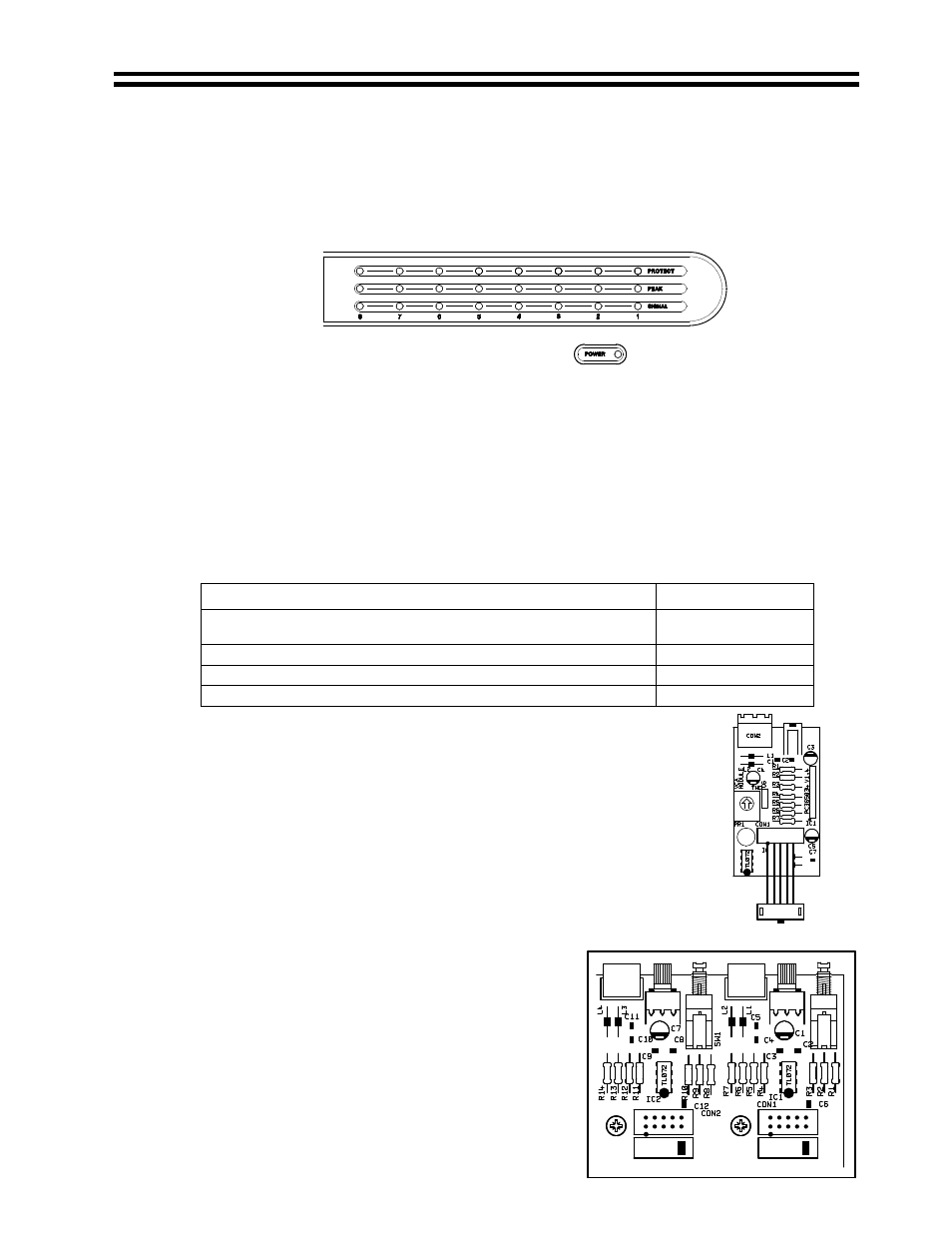
The front panel of the CX-A850 has an array of LED’s that indicate the status of all eight
channels (see Fig 6).
The lower green ‘signal’ LED illuminates when a signal is detected, the yellow 'peak' LED will
illuminate when the amplifier’s DCP is operating and the top red ‘protect’ LED indicates that
the protection relay has disconnected the load. Please note that it is normal for all four red
LED's to illuminate for approximately five seconds when the unit is switched on, indicating
operation of the switch-on delay circuitry. The green ‘power’ LED at the bottom right of the
front panel illuminates when the power is switched on.
10
Power Supply Capacity
The CX-A850 has up to 100mA of available current for use with additional modules.
Exceeding this limit will cause temporary power supply failure. Use the table below to verify
your proposed system does not exceed this limit.
Module Name
Current Required
BOSE® EQ cards: M8, M32, MA12, 402, 502A, 802, MB4, MB24,
502B, 502BEX
12mA
BOSE® EQ cards: LT3202, LT4402, LT9402, LT9702
17mA
BOSE® EQ card: M16
24mA
VCA-5
9mA
11
VCA Modules
A single channel VCA module ‘VCA-5’ is available as a plug-in option for
each of the eight channels. When a VCA-5 is installed to a channel it
allows the channel to be controlled remotely with the optional RL-1
remote plate.
The circuitry uses the industry standard 'Thats 2150A' VCA providing
very low distortion and up to 90dB attenuation. The VCA module can be
wired to provide muting by using an auxiliary relay connected to a fire
alarm control panel. Contact our technical department for further details.
12
VCA Module Installation
1. Turn the power off and remove the mains cable
2. Remove the top panel
3. Select the required PCB mounted VCA connector and
remove its jumper (see list below & Fig 8)
CON1 = Channel 1
CON5 = Channel 5
CON2 = Channel 2
CON6 = Channel 6
CON3 = Channel 3
CON7 = Channel 7
CON4 = Channel 4
CON8 = Channel 8
4. Unscrew the relevant blanking plate from the rear of the unit
& retain the screw.
Fig 8
Fig 6
Fig 7