2 general, 3the rj45 connection, 4 schematic diagram – Cloud Electronics SS16 User Manual
Page 3
2
Sub Station 16-R: Installation and operation manual
1 Safety
Notes
• Do not expose this unit to water or moisture
• Do not expose the unit to naked flames.
• Do not block or restrict any air vent
• Do not operate the unit in ambient temperatures above 35
o
C
• There are no internal user adjustable parts. Do not remove covers.
• Refer any servicing to qualified service personnel.
• Do not replace the power transformer with any other type
For more detailed information refer to the rear of the manual.
2 General
The Sub Station 16-R increases the capacity of the Pump Station 16-R by up to sixteen RH-8 or
WP-8 remote control units. Each Pump Station 16-R can accommodate up to 15 Sub Station
16-R’s allowing a maximum system capacity of 256 remote control units. The system is wired
in a ‘daisy chain’ format; the cable for this comes supplied with each Sub Station 16-R.
The remote control units for use with the Sub Station 16-R are fitted with a headphone socket,
rotary source select switch and volume control. The RH-8 is designed to fit the majority of
exercise machines and can be wall mounted. The WP-8 is a dedicated wall-mounting version
of the RH-8 with provision for driving low power speakers.
Eight-core Category 5 (4-pair Cat- 5) cable should be used to wire each remote back to the Sub
Station 16-R. The RH-8 comes supplied with a 3m RJ45 patch cable that can be terminated
into a wall or floor mounted RJ45 socket (commonly used as part of a computer network).
The front panel controls on the Sub Station 16-R are reduced to a power switch with all
input/output terminations mounted on the rear panel. The unit can be located in a protected
area with the remote control units positioned in the most appropriate location.
3
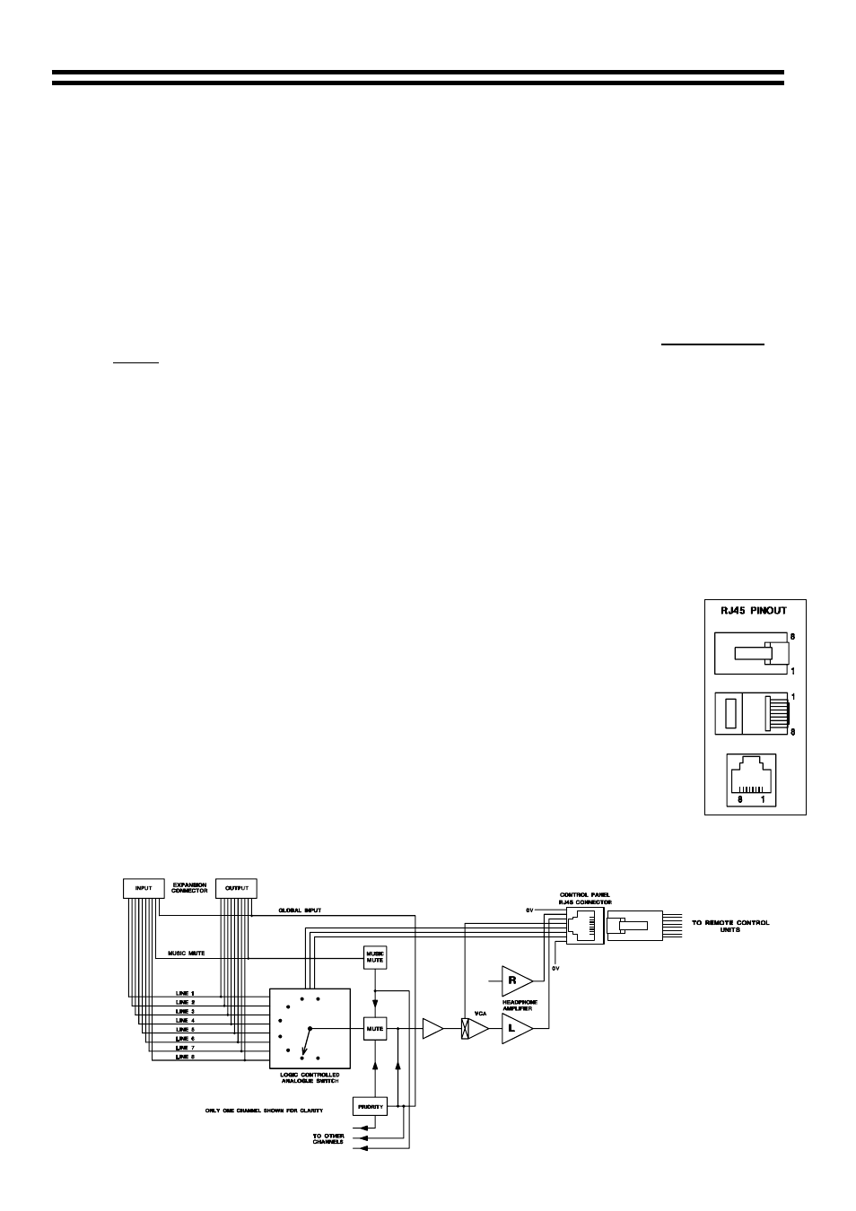
The RJ45 Connection
The RJ45 plug is a compact 8-pole connector primarily designed for CAT5 cable.
Special tools are available making termination both easy and quick.
1) Strip approximately 1” of outer sheath from the cable.
2) Remove extraneous material such as plastic wrap or foil screen from the 8
exposed cores but do not strip their sheaths.
3) Cut the 8 exposed cores down so that when the cable is inserted into the RJ-
45 the outer core can be held by the plugs cable retention system.
4) Insert the 8 cores into the RJ-45 plug fully making sure that they are all
correctly arranged. Information on the correct arrangement of cores for the
RH-8 can be found in section 6 and the WP-8 details are in section 7.
5) Place the plug/cable assembly into the crimp tool and operate the mechanism.
6) You should now have a firmly connected cable assembly ready for installation.
The above notes are for guidance only: always follow the instructions supplied with the tool
4 Schematic
Diagram
16-07-02 V2.1