Cloud Electronics SS16 User Manual
Page 6
Sub Station 16-R: Installation and operation manual
5
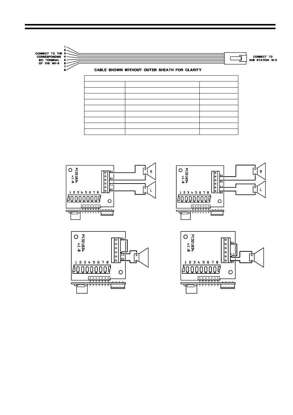
Cable for Hard Wiring a WP-8 to a Sub Station 16-R
Cable Information for Wiring the WP-8
WP-8 (IDC)
Sub Station 16-R (RJ45)
CAT 5*
Pin 1
Pin 8
Brown/White
Pin 2
Pin 7
White/Brown
Pin 3
Pin 6
Green/White
Pin 4
Pin 5
White/Blue
Pin 5
Pin 4
Blue/White
Pin 6
Pin 3
White/Green
Pin 7
Pin 2
Orange/White
Pin 8
Pin 1
White/Orange
*The CAT 5 colour is described as the dominant colour first with the tracer second.
The following diagrams show how to wire either speaker output in stereo or mono.
Permanent Speaker Network (Stereo) Switched Speaker Network (Stereo)
Permanent Speaker Network (Mono)
Switched Speaker Network (Mono)
The WP-8 will provide 150mW of power in stereo configuration and 300mW in mono into 8
Ω
speakers. The impedance of the speakers is not critical however the unit will deliver more
power into speakers with an impedance of >8
Ω.
Be vigilant when wiring the WP-8 since wiring errors can cause flawed operation. If a problem
is experienced, turn off the power, disconnect the WP-8 and double-check the wiring against
the WP-8 cable diagram on the previous page.
The Cloud WP-8 is designed to be wall mounted. The WP-8 is the same physical size as a
single UK electrical socket (13A Type) and can be mounted in the recessed back box provided
or be surface mounted in a standard 25mm deep housing.
16-07-02 V2.1
The Cloud WP-8 is fitted with a 3.5mm stereo jack socket that will accept a pair of stereo
headphones. We recommend the use of headphones with 32-ohm impedance for example, the
Cloud CP-32.