7 wp-8 installation – Cloud Electronics SS16 User Manual
Page 5
4
Sub Station 16-R: Installation and operation manual
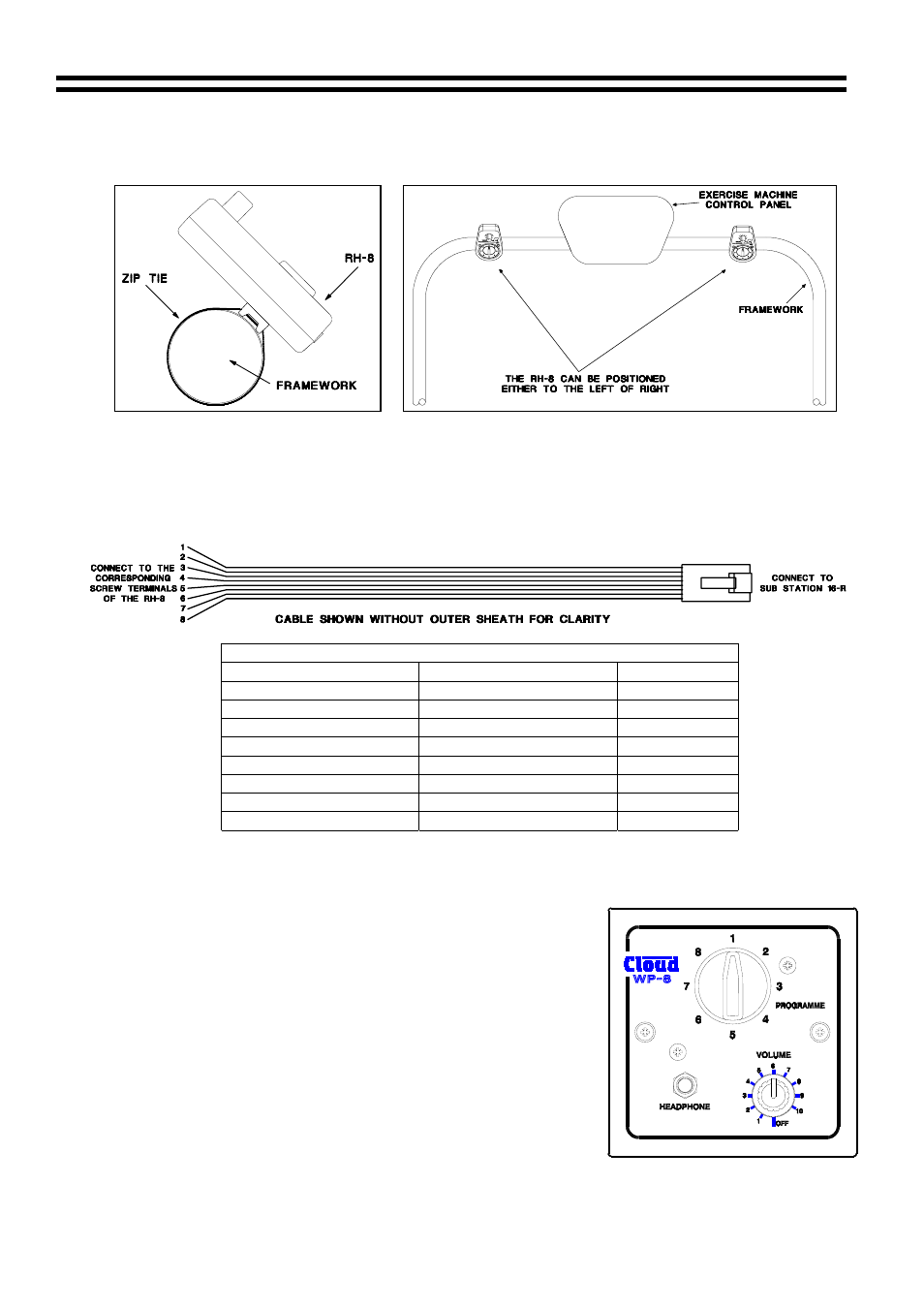
When mounted to framework the RH-8 should be positioned at 45
o
(see left hand diagram
below), Ideally the RH-8 should also be positioned to one side of the user instead of directly in
front (See right hand diagram below)
When mounted directly on to a wall or perhaps the bulkhead of an exercise machine, it may be
preferable to hard wire a cable directly to the RH-8 using its internal screw terminals, a diagram
and wiring information for this are shown on the following page.
Cable for Hard Wiring an RH-8 to a Sub Station 16-R
Cable Information for Hard Wiring the RH-8
RH-8 (Screw Terminals)
Sub Station 16-R (RJ45)
CAT 5*
Pin 1
Pin 8
Brown/White
Pin 2
Pin 7
White/Brown
Pin 3
Pin 6
Green/White
Pin 4
Pin 5
White/Blue
Pin 5
Pin 4
Blue/White
Pin 6
Pin 3
White/Green
Pin 7
Pin 2
Orange/White
Pin 8
Pin 1
White/Orange
*The CAT 5 colour is described as the dominant colour first with the tracer second.
7 WP-8
Installation
The WP-8 is a dedicated wall-mounting unit that has all of the
features of the RH-8 and provision for low power speakers.
The module is primarily aimed at scenarios such as tanning
suites and treatment rooms where users may wish to listen to
music. The WP-8 has two low impedance, low power speaker
outputs each with a different operation:
• The first is a normal low impedance speaker output.
• This second provides a similar low impedance output that is
disconnected when headphones are connected to the WP-8.
The WP-8 should be wired directly to the equipment rack
using unscreened ‘Category 5’ cable (4 pair CAT 5), an IDC
insertion tool will be required to connect the WP-8 to the CAT-
5 cable. Cable length should not exceed 100m (328ft).
16-07-02 V2.1