4input facilities – Cloud Electronics CXA200 User Manual
Page 4
CX-A200 I
NSTALLATION AND OPERATION MANUAL
3
4
Input Facilities
All four inputs are balanced and use 3 pin XLR type connectors. All inputs are wired to
the standard convention of pin 1 ground, pin 2 in-phase, pin 3 reverse phase, with the
shell of the connector connected to the chassis. If the unit is operating in a location which
has a high level of electrical or magnetic disturbance or is close to a TV or radio
transmitter, we suggest that the input cable screen be connected to the shell of a metal
XLR type connector. If the signal is from an unbalanced source, connect pin 3 to pin 1
(ground) inside the XLR type connector and use pin 2 as hot.
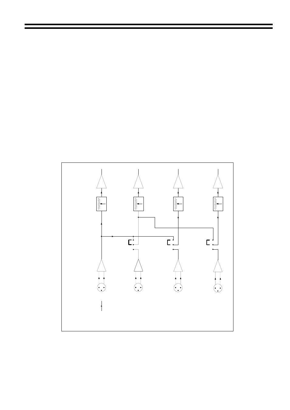
Each input has a level control adjacent to the respective XLR type connector. PCB
mounted jumpers provide input routing on channels 2, 3 & 4 allowing a wide variety of
input routing configurations. See the schematic diagrams showing details of various
routing possibilities.
In its default configuration, the unit operates as four independent amplifiers.
Two stereo pairs, driven from one stereo source and four channels driven from one mono
source are also possible together with a combination of the two by suitably configuring
the input routing jumpers.
1
2
3
4
1
2
1
3
2
4
INPUT 1
1
2
3
4
POWER
AMPLIFIER
LEVEL
CONTROL
SOURCE
JUMPERS
INPUT
AMPLFIER
FROM MONO SOURCE
FOUR CHANNELS DRIVEN FROM ONE MONO SOURCE