10 fitting a vca module, 11 remote level plate connections – Cloud Electronics CXA200 User Manual
Page 7
CX-A200 I
NSTALLATION AND OPERATION MANUAL
6
circuitry uses the industry standard 'Thats 2150A' VCA providing very low distortion and
up to 90dB attenuation. The VCA module can be wired to provide muting by using an
auxiliary relay connected to a fire alarm control panel. See section 11 'Remote Level
Plate Connections' for wiring details.
10
Fitting a VCA Module
Remove the power cable before commencing. Remove the top panel from the CX-A200
then remove the relevant connector cover from the rear panel of the unit. Locate the 10
pin male header (CON1 for inputs 1 & 2 and CON2 for inputs 3 & 4) then remove the two
jumpers from the 10 way header (male connector). Remove the PCB fixing screw(s)
adjacent to the 10 way connector and fit the two 40mm M3 mounting spacers into the two
positions next to CON1 or CON2. Carefully position the VCA module so that the 4 pin
connector is located just through the hole in the rear panel and locate the 10 pin female
ribbon connector on the module accurately on to the header. Make sure that the module
is accurately positioned and check that the connector is mating with all 10 pins. Secure
the module with the two M3 screws provided and replace the top panel.
11
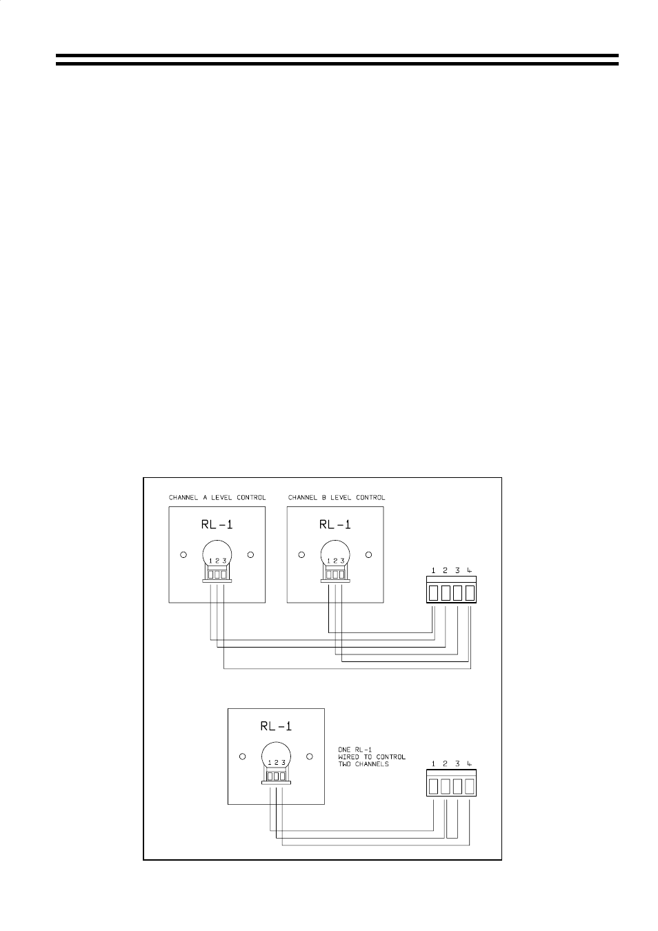
Remote Level Plate Connections
The VCA module is a two channel device providing voltage controlled level adjustment for
two independent channels or one stereo pair. The 4 pole connector can be wired to allow
two RL-1 level plates to control individual channels or one RL-1 controlling two channels
simultaneously for stereo applications. Use two core screened cable to interconnect the
remote level plates.