Comtech EF Data SDM-9220 User Manual
Page 131
Universal E&M/PTT Interface Card
Memotec Inc.
9-3
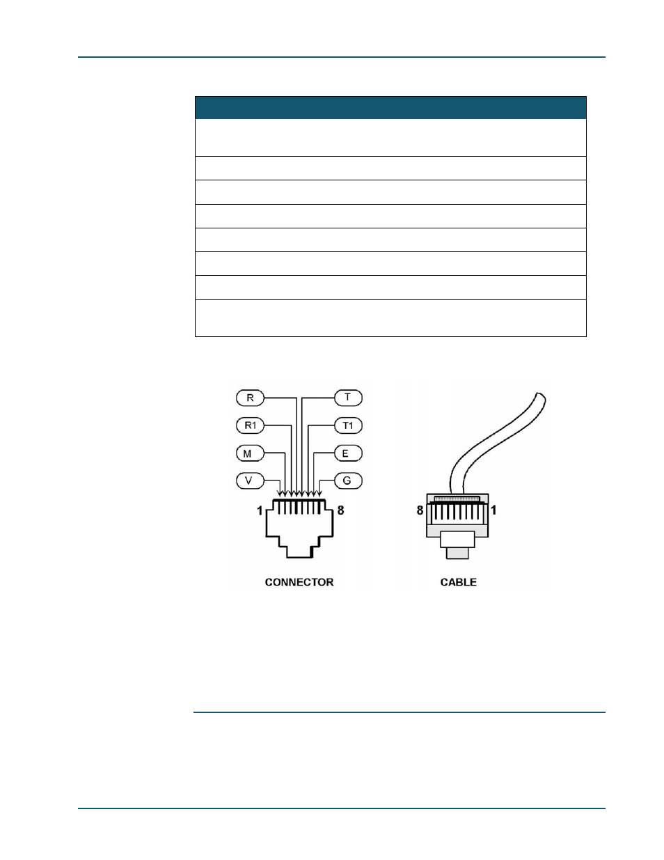
The following table describes the RJ-45 pinout for an E&M/PTT port.
To connect this cable:
1.
Connect one end of the cable to the RJ-45 connector on the interface card.
2.
Connect the other end to the RJ-45 connector on your equipment.
As an alternative, you can cut it off and punch on a Telco/PTT block termination.
NOTE:
You must install a ferrite on each cable connected to an E&M/PTT port
on an SDM-9220 or SDM-9230 (both UAC and DC models) in all coun-
Pin No.
Usage
Description
1
V
Isolated and current limited voltage source output
(+24V or +48V or -24V or -48V)
2
M
Control Signal In
3
R1
Voice In (Transmit Ring)
4
R
Voice Out (Receive Ring) two-wire connection
5
T
Voice Out (Receive Tip) two-wire connection
6
T1
Voice In (Transmit Tip)
7
E
Control Signal Out
8
G
Ground return of isolated and current limited voltage
source
Table 9-1: RJ-45 pinout for the Universal E&M/PTT interface card
Figure 9-1: RJ-45 Pinout (female jack) for Universal E&M/PTT Interface Card