10 drop & insert breakout panel – Comtech EF Data SDM-309B User Manual
Page 111
M&C and Interfaces
SDM-309B Satellite Modem
4-4–34
MN/U-SDM309B Rev. #
4.2.2.10 Drop & Insert Breakout Panel
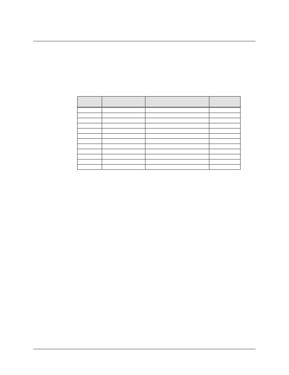
The Drop and Insert Breakout Panel supports the use of the drop and insert channel unit
in the SDM-309 modem. Connections between the breakout panel and other equipment
are made through front and rear panel connectors. These connectors are listed in Table 4-
2. The location of these connectors are shown in Figure 4-12.
Table 4-2 Breakout Panel Connectors
Ref
Desig.
Connector Type
Name
Pinout
Section
J1
15 PIN “D”
DROP DATA INPUT
4.2.2.10.1
J2
15 PIN “D”
DROP DATA OUTPUT
4.2.2.10.2
J3
15 PIN “D”
INSERT DATA INPUT
4.2.2.10.3
J4
15 PIN “D”
INSERT DATA OUTPUT
4.2.2.10.4
J5
BNC
DROP DATA INPUT
4.2.2.10.5
J6
BNC
DROP DATA OUTPUT
4.2.2.10.6
J7
BNC
INSERT DATA INPUT
4.2.2.10.7
J8
BNC
INSERT DATA OUTPUT
4.2.2.10.8
J9
BNC
EXT REF CLOCK
4.2.2.10.9
J10
25 PIN “D”
ESC CHANNEL
4.2.2.10.10
J11
TERM. BLOCK
FAULTS
4.2.2.10.11
J12
50 PIN “D”
DATA INTERFACE
4.2.2.10.12