9 ibs interface breakout panel – Comtech EF Data SDM-309B User Manual
Page 94
SDM-309B Satellite Modem
M&C and Interfaces
MN/U-SDM309B Rev. #
4-4–17
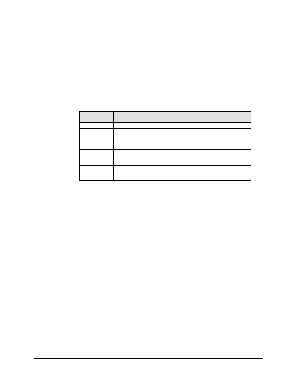
4.2.1.9 IBS Interface Breakout Panel
The IBS Breakout Panel supports the use of the SDM-309 modem with an IBS/M1200P
Channel Unit. Connections between the breakout panel and other equipment are made
through front and rear panel connectors. These connectors are listed in Table 4-1. The
location of these connectors are shown in Figure 4-6. Figure 4-7 shows the schematic
diagram for the IBS Interface Breakout panel. The assembly number for the breakout
panel is AS/1030.
Table 4-1
Ref Desig.
Connector Type
Name
Pinout
Section
J1
50 PIN “D”
IBS TERR. INTERFACE
4.2.1.9.1
J2
37 PIN “D”
RS422 INTERFACE
4.2.1.9.2
J3
CNV 35 PIN
V.35 INTERFACE
4.2.1.9.3
J4
25 PIN “D”
ENGINEERING SERVICE
CHANNEL
4.2.1.9.4
J5
15 PIN “D”
G.703 INTERFACE
4.2.1.9.5
J6
BNC
EXT REF CLOCK
4.2.1.9.6
J7
BNC
SEND DATA
4.2.1.9.7
J8
BNC
RECEIVE DATA
4.2.1.9.8
TB1
TERMINAL
BLOCK
ALARMS OUTPUT
4.2.1.9.9