External connectors, External connections, Chapter 3. external connectors – Comtech EF Data SDR-54A User Manual
Page 23: 1 external connections
Chapter 3. External Connectors
This chapter provides a description of external connections.
3.1 External
Connections
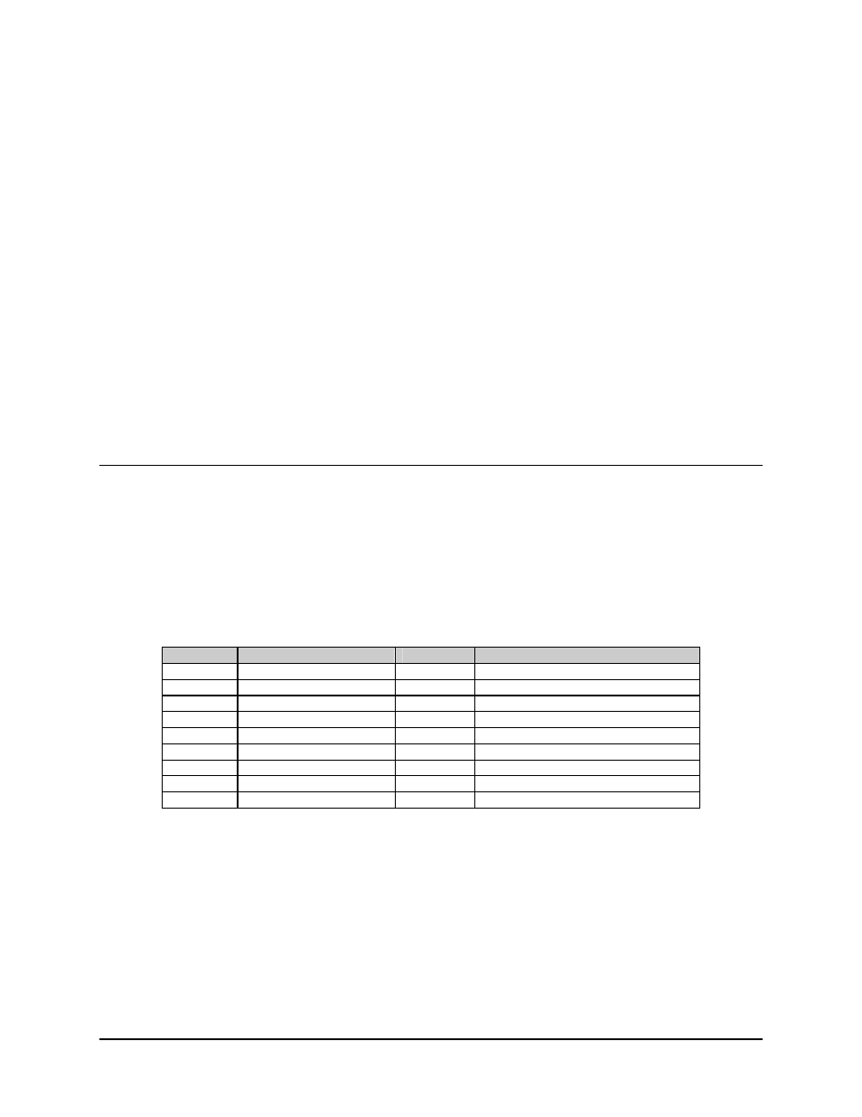
Connections between the demodulator and other equipment are made through external
connectors. These connectors are listed in Table 3-1, and their locations are shown in
Figure 3-1 and Figure 3-2. The use of each connector is described in the following
paragraphs.
Table 3-1. External Connectors
Ref. Desig.
Name
Type
Function
J1
RF INPUT
F coax
LNB input/LNB power
J2
FAULT
9-pin D
External Fault Status
J3
M&C
9-pin D
Configuration and Status (RS-232)
J4
DATA OUT (RX Data)
25-pin D
RS-232 or RS-422 Selectable
*J5
DEMUX T1 through T4
25-pin D
DEMUX Outputs T1 through T4
*J6
DEMUX T5 through T8
25-pin D
DEMUX Outputs T5 through T8
None
M&C REMOTE
9-pin D
Remote Configuration and Status
None
PRIME POWER
Standard
AC Power Input
None
GND
#10-32
Chassis Ground
*Note: J5 and J6 are optional.
3–1