Descrambler, 2 descrambler – Comtech EF Data SDR-54A User Manual
Page 48
SDR-54A Satellite Demodulator
Revision 4
Reed-Solomon Option
MN/SDR54A.IOM
Design guidelines are in accordance with IESS-308/309 (refer to Table 6-1).
Options for the Rx required Reed-Solomon PCB contain the following
• Self-synchronizing Descrambler
• Variable Deinterleaver Depth (8 or 16)
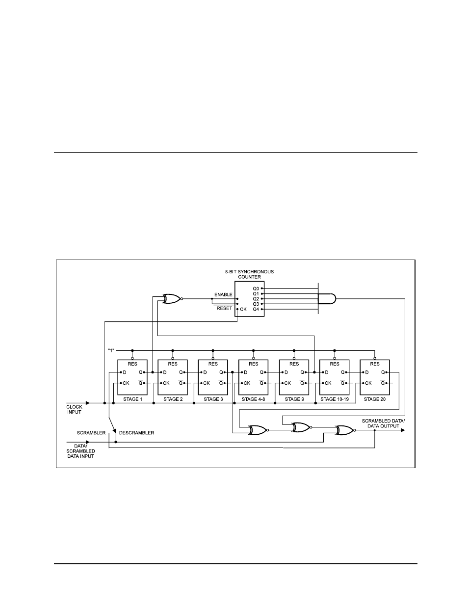
6.2 Descrambler
The descrambler used in the Reed-Solomon assembly is a 2
20
-1 descrambler. It has an
adverse state detector, reset by XOR’ ing bits 11 and 19. The adverse state detector counts
from 0 to 31. At count 31, it inserts a one into the descrambler. The tap points into the
descrambler are 0 and 17. The data is inverted before it is sent through the descrambler.
Refer to Figure 6-2, which shows a block diagram of the V.35 Self-Synchronizing
Descrambler.
Figure 6-2. V.35 Self-Synchronizing Descrambler
6–2