Power supply replacement, Light sensor replacement, Power supply replacement light sensor replacement – Daktronics Galaxy AF-3500/3550 User Manual
Page 32
28
Parts Replacement
Power Supply Replacement
Tool required: Phillips screwdriver
Galaxy displays use 135-watt
power supplies that run up to four
modules (eight modules in 34 mm
monochrome displays).
Each module is connected to a
wire harness on the power supply
by a Mate-n-Lok
®
cable. Refer to
Figure 25 for an example.
Complete the following steps to
replace a power supply:
1. Turn off power to the
display.
2. Remove the module directly in front of the appropriate power supply.
3. Disconnect the Mate-n-Lok
®
connectors from the power source as well as those going to the modules.
Be sure to label each connector so that it can be properly reconnected.
4. Loosen the screw holding the power supply bracket to the cabinet upright and lift it off the hooks.
5. Carefully pull the power supply out of the cabinet.
6. Move the new power supply into place and tighten the screw on the support bracket.
7. Reconnect all the Mate-n-Lok
®
plugs so that each module will receive power.
Light Sensor Replacement
Tools required:
3
/
16
" nut driver, Phillips screwdriver
The light sensor assembly is mounted inside the bottom-left edge of the
cabinet. Refer to
Figure 10 for location.
If the light sensor fails, only the circuit board needs to be replaced.
Remove the bottom-left module on the display to access the light sensor.
To replace a light sensor circuit board as shown in
these steps:
1. Remove the screws that hold the light sensor to the cabinet.
2. Remove the #4-40 nuts securing the circuit board to the plate.
3. Remove the standoffs and attachment screws from the board.
4. Disconnect the four electrical wires on the sensor by unscrewing
each screw that holds a wire in place. Note the order the wires
are connected so they can be reconnected in the same locations
on the replacement.
5. The light sensor plug on the controller does not need to be detached.
6. Reattach the new circuit board, following these steps in reverse.
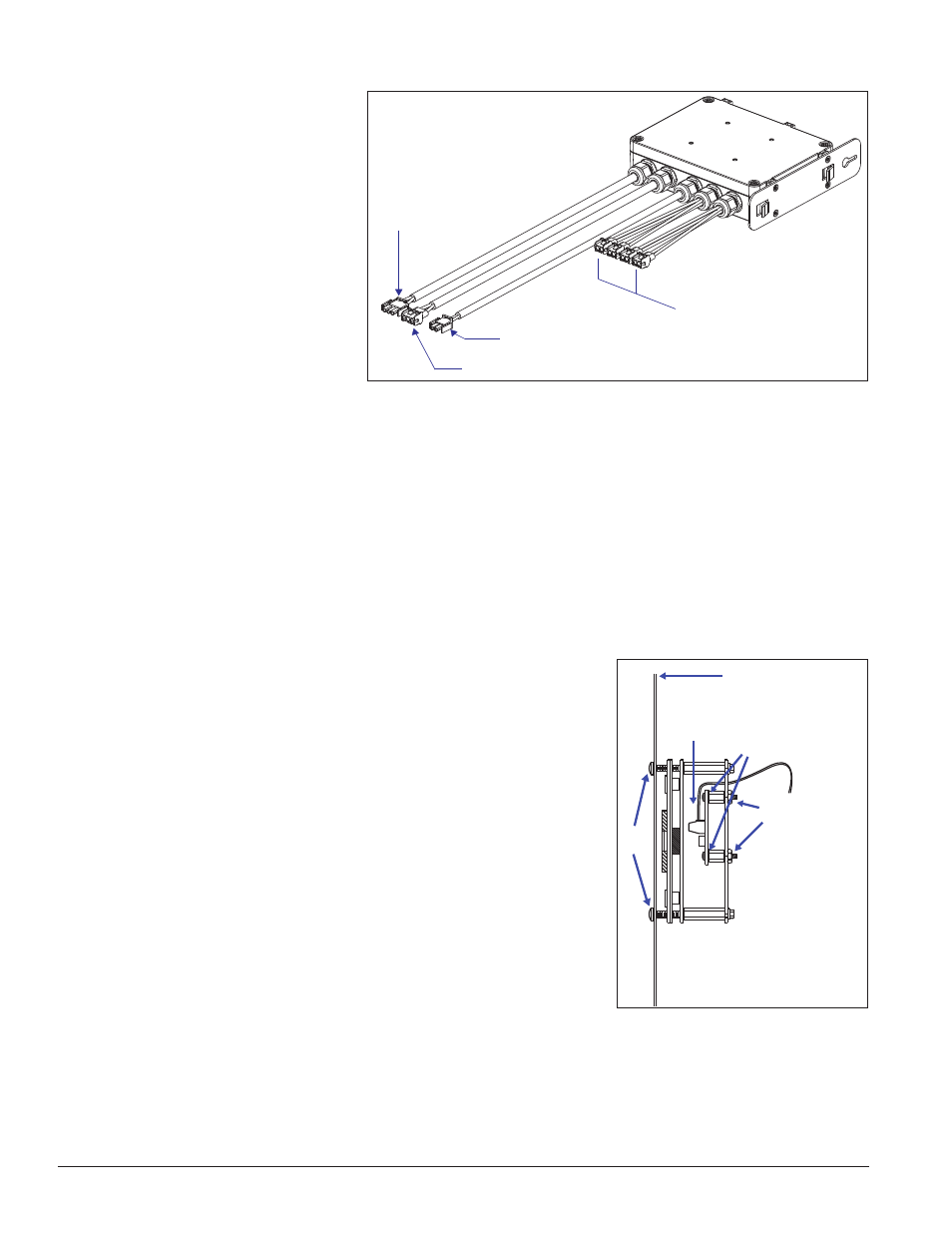
DC Outputs (To Modules)
AC Input
(From Power
Source)
AC Output (To Next Power Supply)
V Adjust (To Initial Module)
Figure 25: Power Supply
1
2
3
4
Front Panel of Display
Figure 26: Light Sensor Assembly