Primary – primary signal termination – Daktronics Venus 1500 Radio – Gen 2 User Manual
Page 23
Primary – Primary Signal Termination
If the location requires two displays that cannot be mounted back-to-back, two primary
displays will need to be installed. In that case, the following connections will need to be
made:
1.
Open the display and locate the controller for these displays.
2.
Route the cable through conduit from the back of the first primary display to the back
of the second primary display. Use one of the knockouts for access, being careful not
to damage any internal components.
3.
Use either a 4-pair signal cable or two 4-conductor, shielded cables to connect both the
signal and the temperature sensor information between displays.
4.
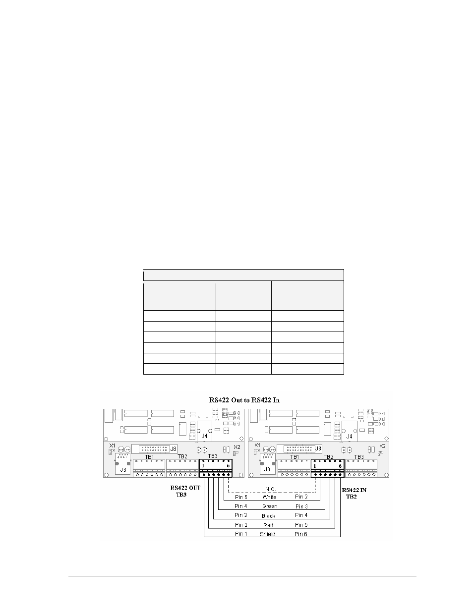
The signal cable will connect from TB3 out on the first primary display to either:
a. A surge board at TB1 in a second primary display.
b. (or) To TB2 on the controller in the second primary display.
Note: In either case, the connections are flipped. See the table for connections on both
displays.
5.
In Figure 22, the signal connections between two controllers are shown.
6.
See the instructions for the Optional Temperature Sensor in the appendix of the
display manual for connections that need to be made for the temperature sensor
termination.
Primary to Primary Connections
Primary
RS422 OUT
(TB3)
Field
Cabling
Primary RS422
IN
(TB2)
Pin 1 (GND)
Shield
Pin 6 (GND)
Pin 2 (D2OUT-N)
Red
Pin 5 (D1IN-N)
Pin 3 (D2OUT-P)
Black
Pin 4 (D1IN-P)
Pin 4 (D2IN-N)
Green
Pin 3 (D1OUT-N)
Pin 5 (D2IN-P)
White
Pin 2 (D1OUT-P)
Pin 6 (Shield)
Pin 1 (Shield)
Figure 22: Connection between Two Primary Displays
Installation Guidelines
21