Appendix a: reference drawings – Daktronics Venus 1500 Radio – Gen 2 User Manual
Page 35
Appendix A: Reference Drawings
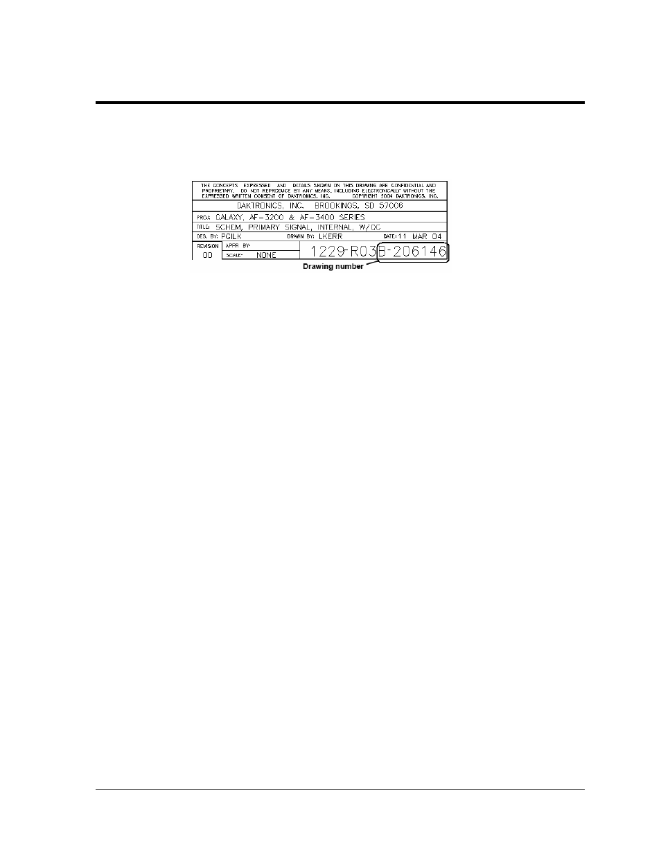
The Daktronics drawing number is located on the bottom right corner of the drawing. Refer to Figure
29 for a sample drawing label with the drawing number circled. The drawings are listed here in
numerical order by the last set of digits and grouped together by drawing size, (A, B).
Figure 29: Drawing Label
System Riser Diagram; Modem/Outdoor Radio, Gen 2 ............................................Drawing A-148606
System Riser; Radio Interface...................................................................................Drawing A-160039
Radio QC Cable Term/Assy, V1500..........................................................................Drawing A-176792
System Riser Diagram; Outdoor Radio, Gen 2 .........................................................Drawing A-185325
System Riser Diagram, Radio Interface, Indoor, Gen 2............................................Drawing A-187988
System Riser, Radio Interface, QC, Gen 2 ...............................................................Drawing A-187998
System Riser Diagram; Radio (Gen 2) QC ...............................................................Drawing A-211606
System Riser Diagram; Modem/QC Outdoor Radio, Gen 2 .....................................Drawing A-242383
System Riser Diagram, Indoor Radio, Gen 2, QC. ...................................................Drawing A-285780
Radio Cable Connections/Assembly .........................................................................Drawing B-161953
Appendix A: Reference Drawings
33