6 power routing in the display, Power routing in the display, Figure 12: two circuit 120 vac wiring – Daktronics Galaxy AF-3400 34 mm Monochrome/RGB User Manual
Page 22: Figure 13: six circuit 120 vac wiring
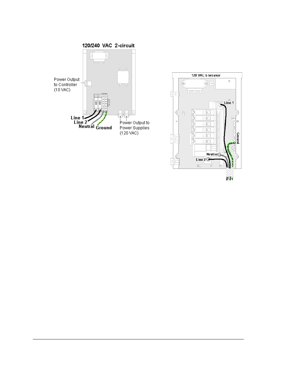
Figure 12: Two Circuit 120 VAC Wiring
Figure 13: Six Circuit 120 VAC Wiring
Note: The four and six circuit displays do not use cage
clamps. Feeders from the main disconnect must be
grounded to the main lugs of the power termination
panel. Refer to Figure 13.
3.6 Power Routing in the Display
Following is a basic overview of power routing. This may vary depending on the pixel
dimensions and LED color of each display. Check for exact power routing on the Shop
Drawing for the specific display.
A general power routing, shown in Figure 14, is summarized as follows. The numbers in this
list correspond with the numbers in the diagram.
1.
Power may terminate to the J-box on the back of the display.
2.
From the J-box, power continues through pre-terminated wires to the power
termination panel, which may include the transformer and filter. Or power may be
directly terminated to the power termination panel.
3.
Power passes through the transformer where 120 VAC voltage is stepped down to 10
VAC for use by the controller.
4.
Power is routed to the power supplies which provide DC voltage to the modules.
Depending on the pixel count and LED color, either 6.5 VDC or 9 VDC power
supplies are used to power the modules.
5.
Power is also sent to the fans and to the thermostat, if installed.
Note: Power supplies are preset to proper voltage levels. Contact Daktronics Customer
Service for proper settings.
Power Installation
14