Controller replacement, Figure 39: typical controller, Figure 40: rotary switches – Daktronics Galaxy AF-3400 34 mm Monochrome/RGB User Manual
Page 50
Controller Replacement
Complete the following steps to remove the controller from the display:
Tools required: 1/8" hex wrench and 3/16" nut driver
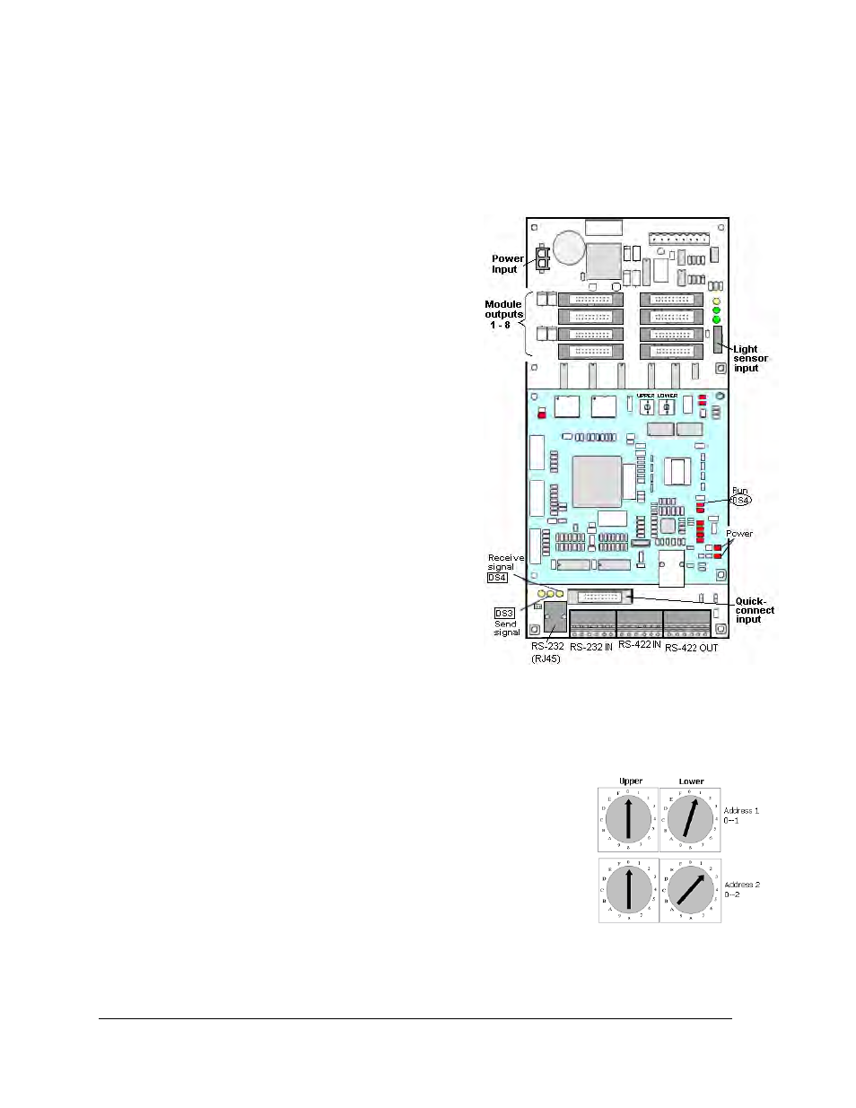
Figure 39: Typical Controller
1. Turn off power to the display.
2. Remove the module directly in front of the
controller in the lower left corner of the
primary display.
3. Disconnect the power plug from power
input jack.
4. Remove all power and signal connections
from the board, carefully pulling them
from their jacks. Label the various cables
and wires as they are removed to insure
their proper replacement.
5. Remove the six nuts holding the board in
place using a
3
/
16
" nut driver.
6. Take note of the address of the controller
and set the same address on the
replacement controller. Refer to the
information following for instructions.
Controller Address Setting
The rotary switches set the hardware address which the software uses to identify that
particular display (Figure 40). Each controller in a network needs a unique address.
Set the switches by rotating them counter clockwise until the arrow
points to the desired number. The display’s power must be turned off
and then turned back on to activate the test mode or to change the
address.
Figure 40: Rotary Switches
Note: Setting both rotary switches to address 0 will activate a Test
Mode. Turn the display’s power off and back on to activate testing.
After testing, set the addresses to numbers other than 0/0. The
software will not communication with a controller set to address 0.
Parts Replacement
42