Modules and drivers, Power supplies, Light detector – Daktronics AF-3400-133,171,216,260 User Manual
Page 33: Modules and drivers -7, Power supplies -7, Light detector -7
Maintenance and Troubleshooting
4-7
Modules and Drivers
Each module contains 28 individual pixels. In the event that a pixel should have to
be replaced, complete the following steps:
1. Open the module door with the defective pixel as described in Section 2.2.
2. Locate the malfunctioning pixel, and remove the 2 pin connector from the
back of the pixel board (squeeze the locking connector in order to release
the connection). Refer to .
3. Remove the four keps nuts from the corners of the pixel board
4. Remove the pixel board
5. Place the new pixel board on the module, and reverse steps one through
four
Power Supplies
Reference Drawing:
Schematic; Power Supply Configuration ..................... Drawing A-215504
Shop Drawings........................................................................ Appendix A
The LED power supplies are located on the lower half of the Galaxy display. The
display specific Shop Drawings provide the location of power supplies in each
block of the display. Power supplies are referred to as Detail (A).
Complete the following steps to remove a power supply from the display:
1. Open the module door to the appropriate section as described in Section
2. Remove the cover from the power supply by removing the screws located
on the bottom section of the enclosure
3. Disconnect and label all the wires connected to the power supply
4. Remove the hardware holding the power supply in place to free the unit.
5. Follow these steps in reverse order to install a new power supply. Refer to
Drawing A-215504 when reconnecting the wires.
Light Detector
Reference Drawings:
Schematic, AF-3400-7 (8)X16(A)-***-*-p, 120, 120/240Drawing B-211433
Shop Drawings........................................................................ Appendix A
The light detector is internally mounted and wired at Daktronics. It is located in the
bottom left corner on the front of the display (refer to the appropriate Shop
Drawings). A 4-conductor cable connects the light detector to the signal termination
panel. The cable is terminated at the terminal block on the light sensor and at the
signal termination panel. Refer to Drawing B-211433.
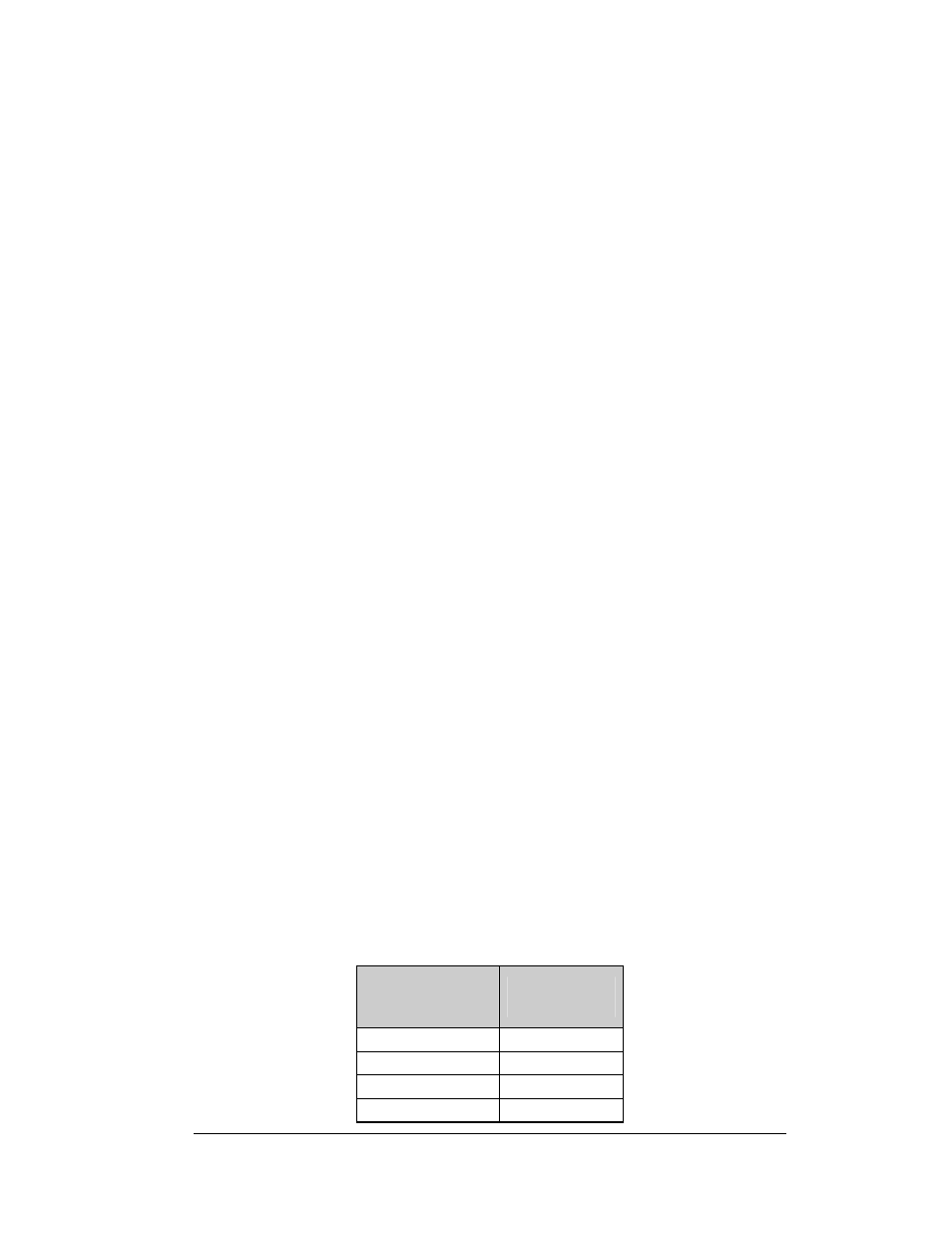
Light Detector
Pin No.
(TB1)
Cable Wires
Color
1 Red
2 Green
3 White
4 Black