Section 7: diagnostics and troubleshooting, 1 controller diagnostics, Section 7 – Daktronics AF-3700-20 RGB User Manual
Page 39: Diagnostics and troubleshooting, Controller diagnostics, Figure 43: controller locations
Section 7:
Diagnostics and Troubleshooting
This section defines the diagnostic LEDs located on the controller and the temperature sensor.
Troubleshooting tips are also provided for solving display problems.
Safety Precautions
Disconnect power when servicing the display.
Qualified service personnel are recommended for servicing internal electronic components.
7.1 Controller Diagnostics
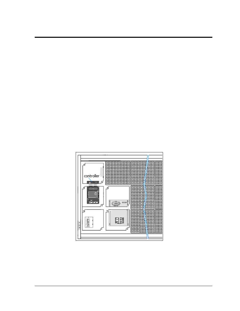
The controller is the “brains” of the display, receiving communication from the computer and
then sending the appropriate information to the modules. The controller is located in the
lower left area (Figure 43) in both single-section and two-section displays. The LEDs on the
controller are able to show whether the power and communication signal are working
properly.
Since the controller is inside the display, a module or two will need to be removed to view
the diagnostic LEDs. To access the interior of the display, refer to Section 6.1 for instructions
and illustrations.
Figure 43: Controller Locations
Remember to disconnect power to the display before accessing the interior.
However, once the modules are removed and wires are found to be safe, power can be
turned back on to view the diagnostic LEDs.
Diagnostics and Troubleshooting
29