Chapter 2 - hardware installation, System board layout, System memory – DFI CD101-N User Manual
Page 9: Chapter 2 chapter 2 - hardware installation, Board layout, Chapter 2 hardware installation
www.dfi .com
9
Chapter 2 Hardware Installation
Chapter 2
Chapter 2 - Hardware Installation
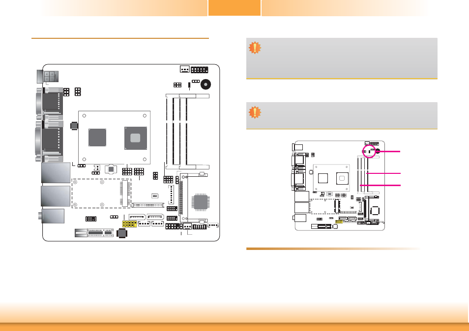
Board Layout
LAN 1
USB 0-1
LAN 2
USB 2-3
Intel
NM10
Intel Atom
SPI Flash BIOS
1
10
12
3
Mini PCIe/mSATA
Select (JP7)
1
3
12
SATA1/mSATA
Select (JP6)
PCIe x1 /
Mini PCIe
Select (JP11)
10
1
3
12
Fintek
F81866AD
1
1
Mini PCIe
1
8
Mic-in
Line-in
Line-out
12
2
1
2
5
6
LVDS Panel
Power (JP9)
USB 0-3
Power
Select (JP3)
1
Clear CMOS Data
(JP4)
1
2
6 5
COM 1 RS232
Power Select
(JP1)
COM 1 RS232/422/485
Select (JP2)
1
2
6 5
1
39
LVDS LCD Panel
2
40
1
ON
4
LVDS Panel
Select (SW1)
LVDS/Inverter
Power
SATA 0
SATA 1
SATA Power
1
4
1
4
USB 4-5
1
9
2
1
2
9
Factory
Test
1
System Fan
DIO
Power
1
4
DDR3_1 SODIMM
DDR3_2 SODIMM
1
2
10
9
Front Audio
1
USB 4-5 Power
Select (JP5)
COM3
COM4
PCIe x1
DIO
1
11
Standby Power LED
Buzzer
1
Power-on Select
(JP10)
CPU Fan
1
Front Panel
1
2
11
12
VGA
DVI-I
COM 2
COM 1
1
2
10
9
1
2
10
9
ASM1442
1
Chassis
Intrusion
DC-in
ATX power (optional)
1
2
5
6
I
2
C
1
LVDS Brightness Control Select
(JP12)
CompactFlash socket
(optional)
D2550/N2800/
N2600
Battery
Realtek
ALC886
1
1
System Memory
DDR3-2
DDR3-1
Standby
Power LED
Features
•
Two 204-pin DDR3 SODIMM sockets (-N2550/-N2800)
•
One 204-pin DDR3 SODIMM sockets (-N2600)
•
Supports 800MHz(-N2600)/1066MHz (-N2550/-N2800) DDR3 SDRAM
• Single
channel
memory
interface
•
Supports maximum of 4GB (-N2550, -N2800)/2GB (-N2600) system memory
Important:
Electrostatic discharge (ESD) can damage your board, processor, disk drives, add-in
boards, and other components. Perform installation procedures at an ESD workstation
only. If such a station is not available, you can provide some ESD protection by wear-
ing an antistatic wrist strap and attaching it to a metal part of the system chassis. If
a wrist strap is unavailable, establish and maintain contact with the system chassis
throughout any procedures requiring ESD protection.
Important:
When the Standby Power LED lit red, it indicates that there is power on the system
board. Power-off the PC then unplug the power cord prior to installing any devices.
Failure to do so will cause severe damage to the motherboard and components.